Bottom end basics for a blown small block Chevy engine build
383ci SBC Build, Part I
By Ryan Manson * clampdowncomp@gmail.com
When it comes to powering that project that you’ve been working on, there are basically three options; buying a crate engine, buying a junkyard motor, or building an engine from scratch. The first option is by far the simplest and for many of us makes the most sense. With a myriad of companies offering crate engines in every form, from benign 285hp 350s to 700hp LS engines, there isn’t much left to desire when it comes to motorvation. It’s literally a plug ‘n’ play situation, especially if the engine has been broken in and comes shipped with a dyno sheet to back the results. Couple that with a decent warranty and there really isn’t a better “bang for your buck” option when it comes to engine selection. The only downside to the crate engine option is that it can be a little pricey. For some of us, $15k is more than we’ll have in the whole project, so that supercharged LSA crate engine just doesn’t fit our budget. Those trying to pinch a few pennies can try their luck at the roulette wheel that is used drivetrain, but it’s “buyers beware” for the most part. That “low mile” LS engine that came from a rearended truck may in reality been some auto shop’s parts hauler driven by an overzealous, lead footed teenager that never saw an oil change in its 300,000 miles. That leads us to the last alternative, building an engine from scratch.
In the past, when it came to building a custom engine, it usually began with a used block, sent off to be machined and either built by the same engine shop or assembled personally by the owner. With one person ordering the parts (owner) and another dictating what the build required (machine shop), sorting through all the technicalities to get the right components the first time could be a daunting task. In a machine where tolerances are measured in the thousandths of an inch, incorrectly spec’d bearings, rings, or pistons could bring the entire build to a screeching halt.
It’s been a while since I built an engine, the Hemi in my F1 being the last, so I thought it time to throw down the gauntlet and build something. While I was mulling over my options, I realized that the last two engine shops that I used were no longer in business. Guys retire, businesses change hands, and the economy hits mom and pop shops the hardest sometimes when it takes a dip. Without a go-to option, I started to broaden my search for alternatives when it came to my engine build. While I could source a short block from a number of dealers, I couldn’t find one that served all my needs.
What I ended up finding however was an even better option; a completely machined engine block, available in a variety of bore and stroke combinations, via Summit Racing. That gave us all the specs we needed to then order up the corresponding rotating assembly that should result in a bulletproof bottom end (provided I don’t screw things up on assembly!). From there, it was a simple manner of choosing heads, valvetrain, ignition and induction components and we were off to the races.
Building an engine in this manner truly cuts the middle man out of the equation (sorry local machine shop) as the block shows up ready for assembly. Bored, line honed, decked, clearanced for the stroker crank, and with all the proper freeze and galley plugs installed, our engine only needed a quick cleaning for good measure before we got to work. Follow along as we showcase the products we’ll be using and how we hope to build a powerful motor with a vintage vibe.
Sources:
Automotive Racing Prodcuts, Inc (ARP) (800) 826-3045 www.arp-bolts.com
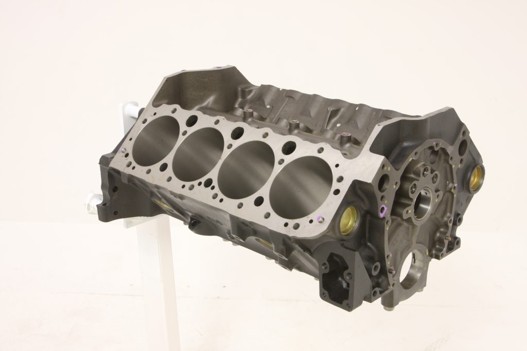
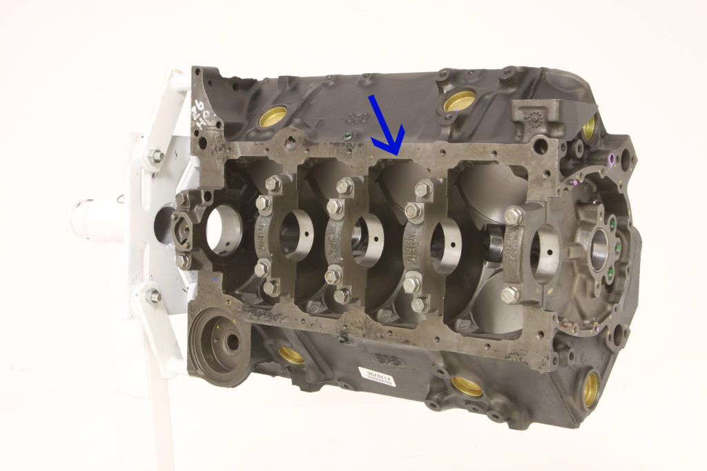
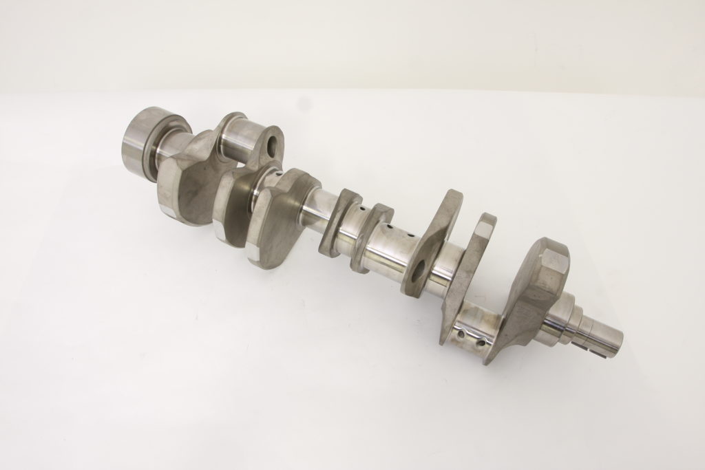
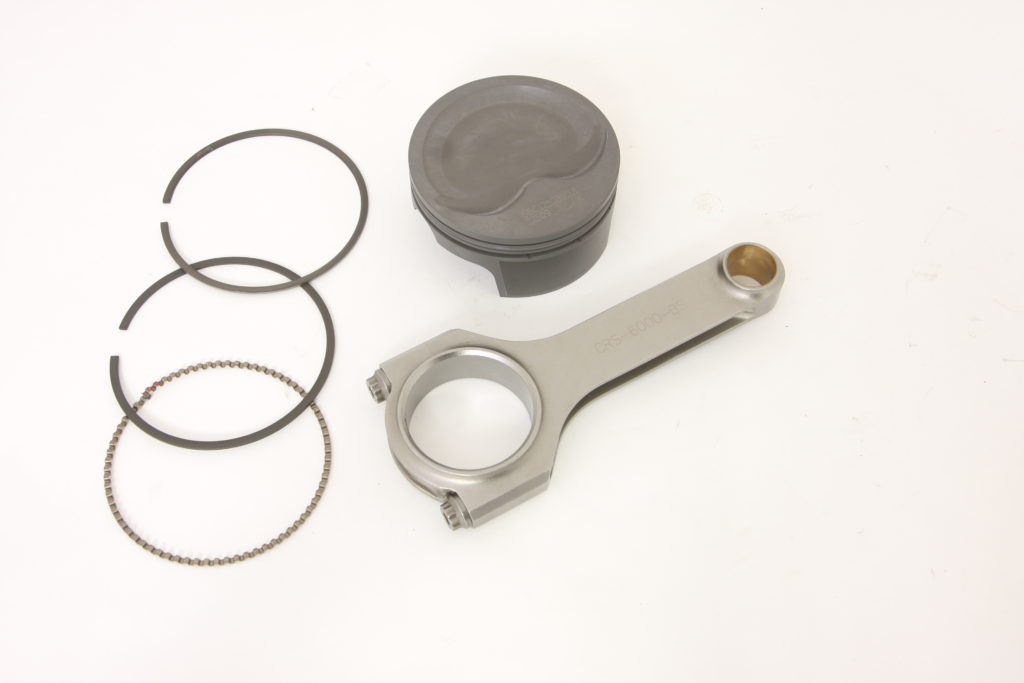
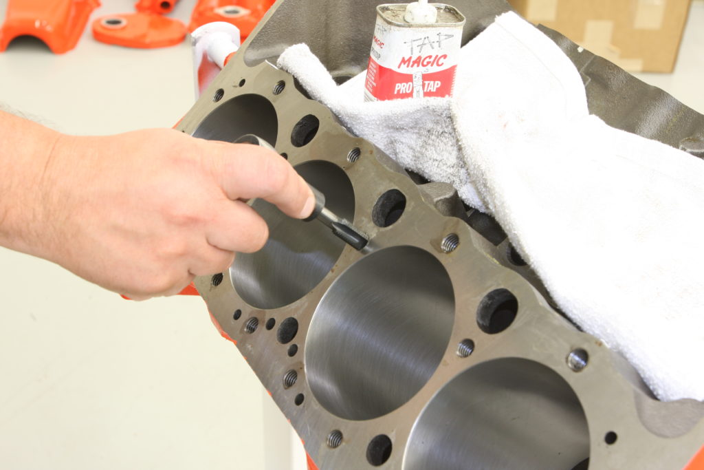
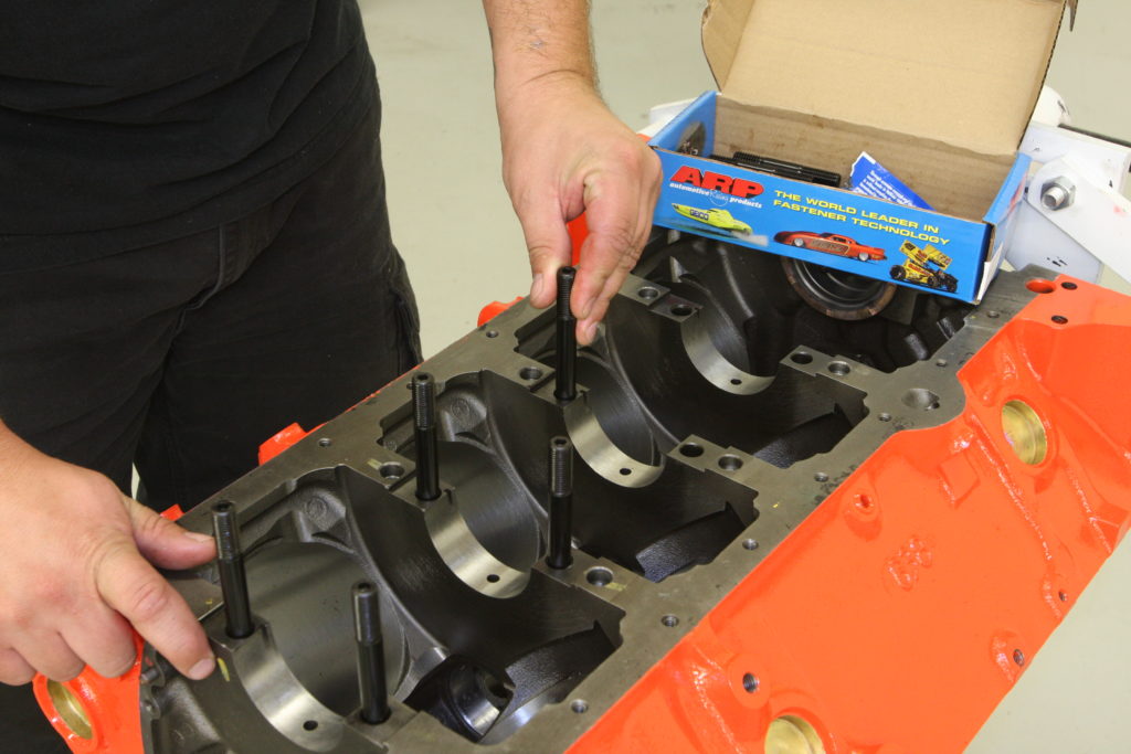
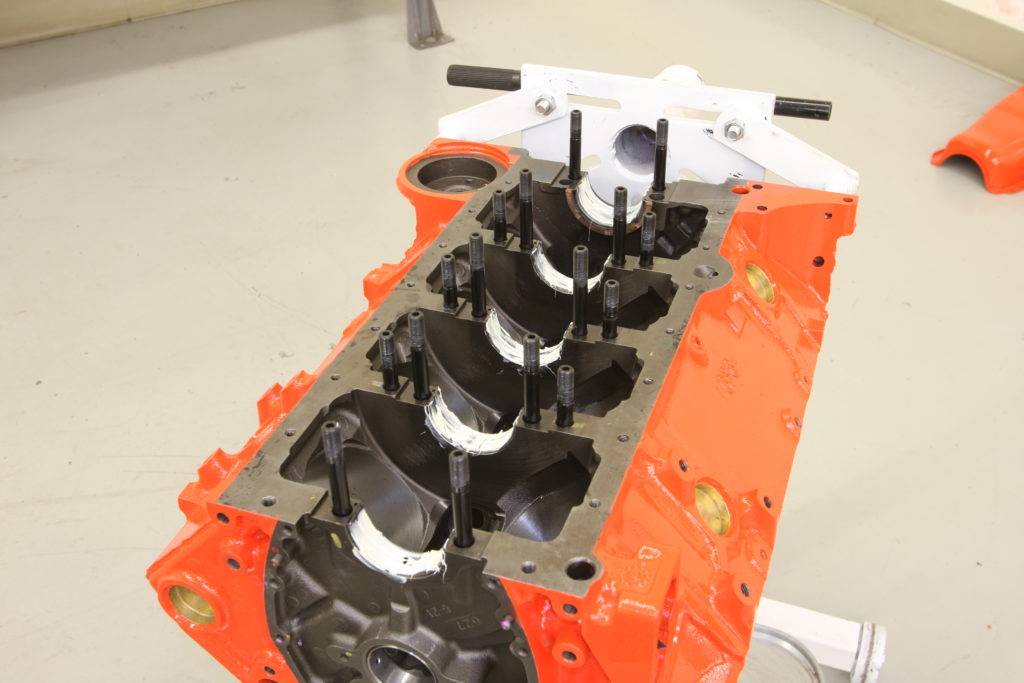
Here’s the block as received from Summit Racing (#SUM-150100-30). It’s ’96-00 Chevy 4-bolt main block machined to spec with a 0.030-inch overbore (4.030-inch), the head surfaces have been decked, the mains have been line honed, the cam bearings have been line bored, and all the needed plugs have been installed. Note that the block features the cast-in provisions for the roller lifter cradle in the valley as well as the threaded cam plate bungs at the front of the block, making it compatible with both roller and flat tappet cams. It will also accept a mechanical fuel pump. The one-piece rear main seal block is ready to be assembled as either a stock stroke 355 or as a stroker 383, when equipped with a 3.750-inch stroke crankshaft, thanks to the clearanced oil pan rails. The main caps are installed, bored, and then line honed to ensure a perfect cradle to house the crankshaft. The factory used three ¼-inch square drive plugs at the rear of the block above the cam plug. If these are still in place when your block returns from the machine shop, chances are the shop never bothered to fully clean the oil galleys, a recipe for disaster. Note that our Summit block features new oil galley plugs (evident by the hex-style head) as well as brass freeze plugs, which are resistant to corrosion. The cam plug is coated steel, which is okay as it won’t (shouldn’t!) come in contact with water.To make things easy, I sourced the rotating assembly from Summit as well, that way I could use their knowledgeable sales staff to help vet any possible incompatibilities. They recommended Eagle Specialty Products Kit (#B12110030), which includes the aforementioned forged 4340 chromoly steel crankshaft, Mahle forged pistons, rings, 6-inch Eagle H-beam rods, and bearings. The -16cc inverted dome pistons, combined with a larger cc cylinder head, will enable us to retain a lower combustion chamber, which is important when building a street engine (especially one equipped with forced induction). Forged from 4340 steel, the Eagle ESP H-beam rods provide exceptional strength while weighing less than their stock brethren. Multi-stage heat treated, x-rayed, sonic-tested, magnafluxed, machined and then shot peened to fully relieve the metal, each rod cap is positively located by alignment sleeves, held together with low profile ARP 2000 rod bolts.With the first step complete, it was time to get on with the actual build prep. This meant breaking out our ARP thread chasing kit, which we used to chase and clean every threaded hole in the block. It’s a tedious process but if you’ve ever built an engine and had a fastener snap in the process, you’ll never do it any other way.
How to Measure Bottom End Clearance
Getting Your Bearings on Your Main Bearings
Building a solid street engine isn’t rocket science, but there is a bit of math involved in order to optimize the performance and reliability of said engine. Whether you’re going with the aforementioned path and buying a machined block and matching components or you’ve farmed out a used block to the local machine shop and had them machine it to match your chosen components, it’s a good idea to measure everything before it all goes together.
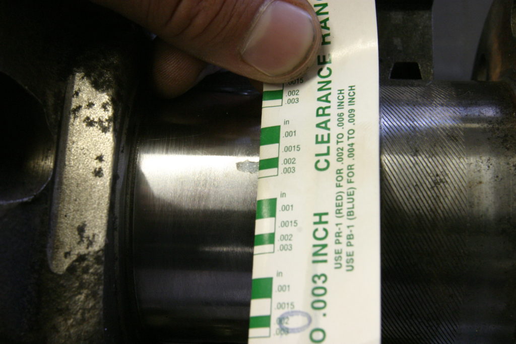
One time-honored method to measuring bearing clearance was to use Plastigage. A strip of the colored stuff is placed in between the bearing and the crankshaft and the assembly is then torqued to spec. It’s then disassembled and the compressed Plastigage strip compared to the product’s provided scale. The result is then compared to the specs determined by the engine’s machine shop and judged as to whether or not the assembly is acceptable.
For most street-driven, moderate horsepower applications, this process is totally satisfactory as it’s only double checking the clearance that should have been machined into the assembly to begin with; it’s strictly done to ensure that the parts have been machined to the specs determined by the machine shop before assembly. It’s a fail-safe step and by far the simplest way to determine safe bearing tolerances, be they crank or rod.
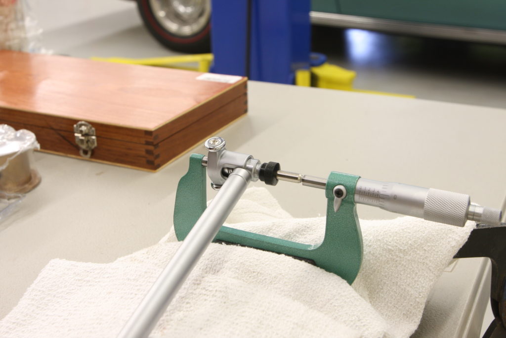
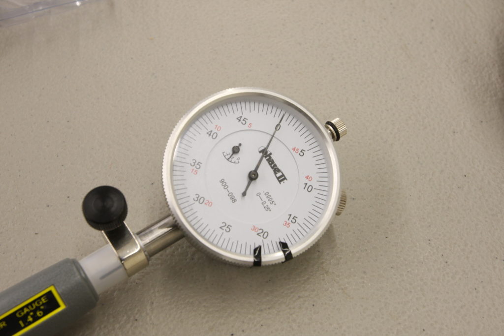
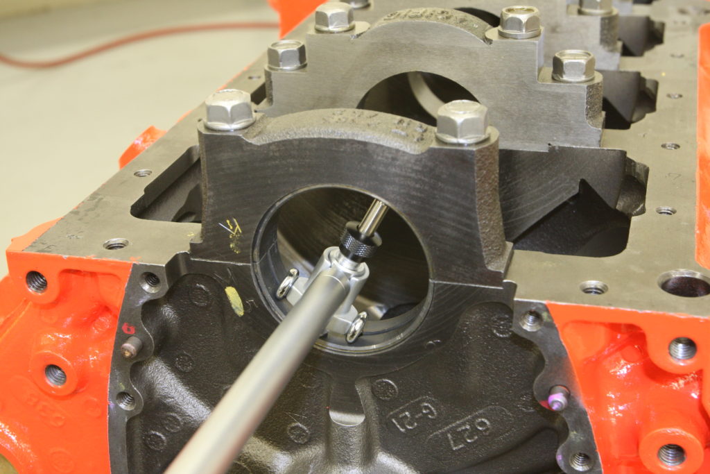
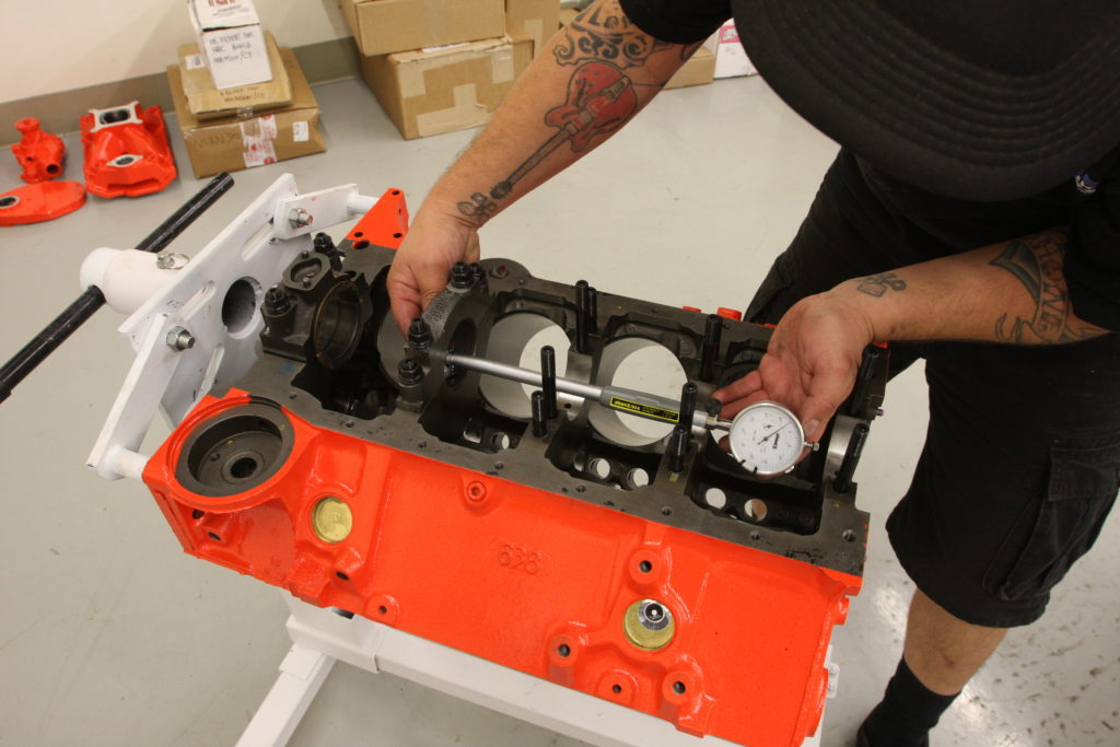
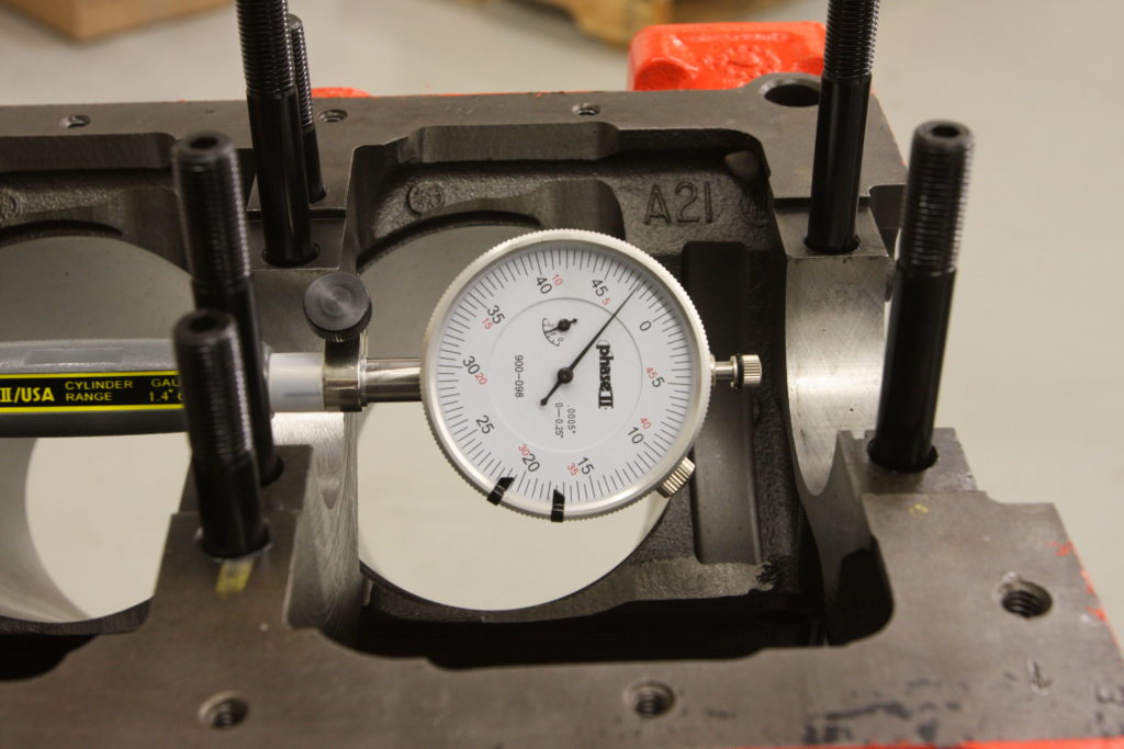
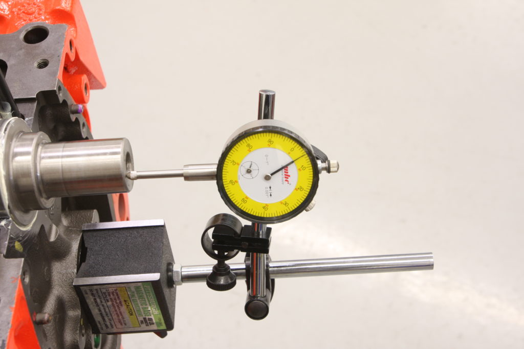
Taking this process a step further requires the use of a few specialized tools. First, the crank main bearing journals are measured using a micrometer. The micrometer is then installed in a vise so that a dial bore gauge can be installed and zeroed to the crank journal’s diameter. Next, the dial bore gauge is inserted in each of the main bearing journals on the block (with the bearings installed and the caps torqued to spec) and the bearing diameter noted. The difference between this measurement and zero on the dial indicator is the bearing clearance. Checking each bearing assembly using this method allows the builder to note the exact clearance and adjust the tolerances to suit (installing over- or under-sized bearings for example).
Using this process ensures that each measurement is determined within the confines of the mic’s ability to accurately measure the crankshaft’s journal. It is possible to yield the same results by measuring the crank journals using the mic and comparing that number with readings taken from each bearing via the dial bore gauge and comparing the two. The problem with this method is that if either or both tools are out of spec a few thou, your clearance number will be affected and incorrect. By setting the dial bore gauge to the mic, it doesn’t matter whether either tool is out of spec as we’re only measuring the difference of the two via the dial indicator. Provided the measurements are taken correctly, it doesn’t matter what the actual measurement of either the crank journal or the bearing assembly is as we’re only concerned with the difference or clearance. CC
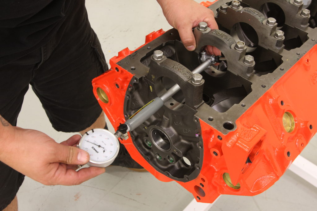
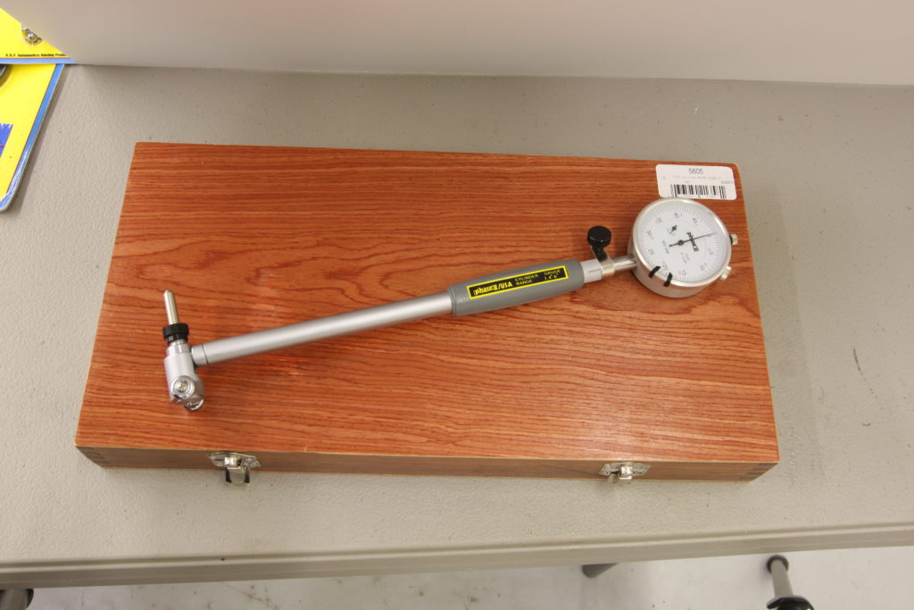
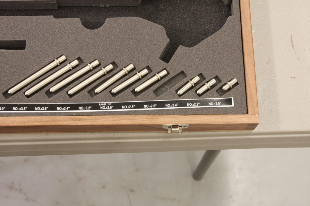
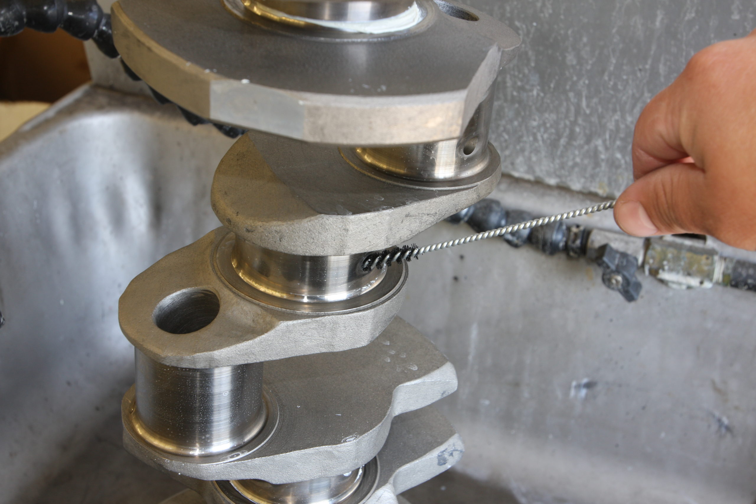
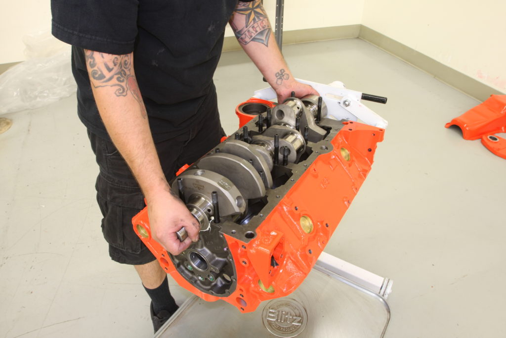
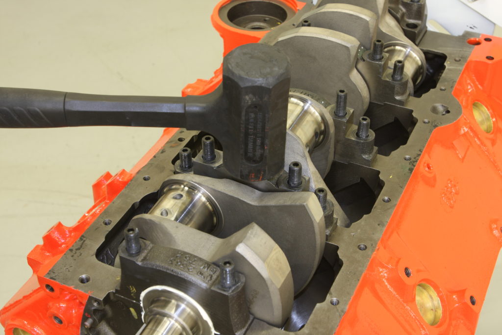
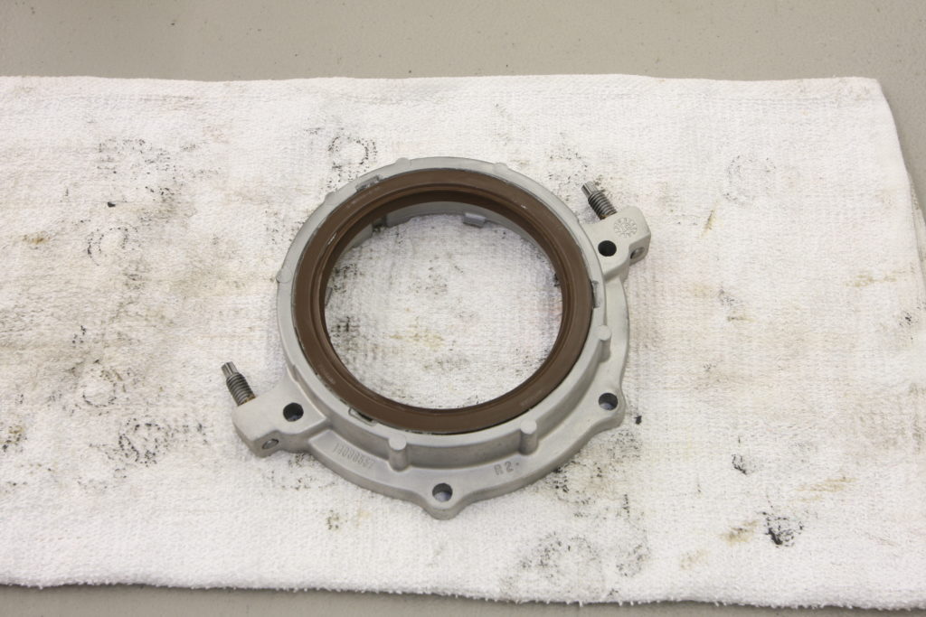
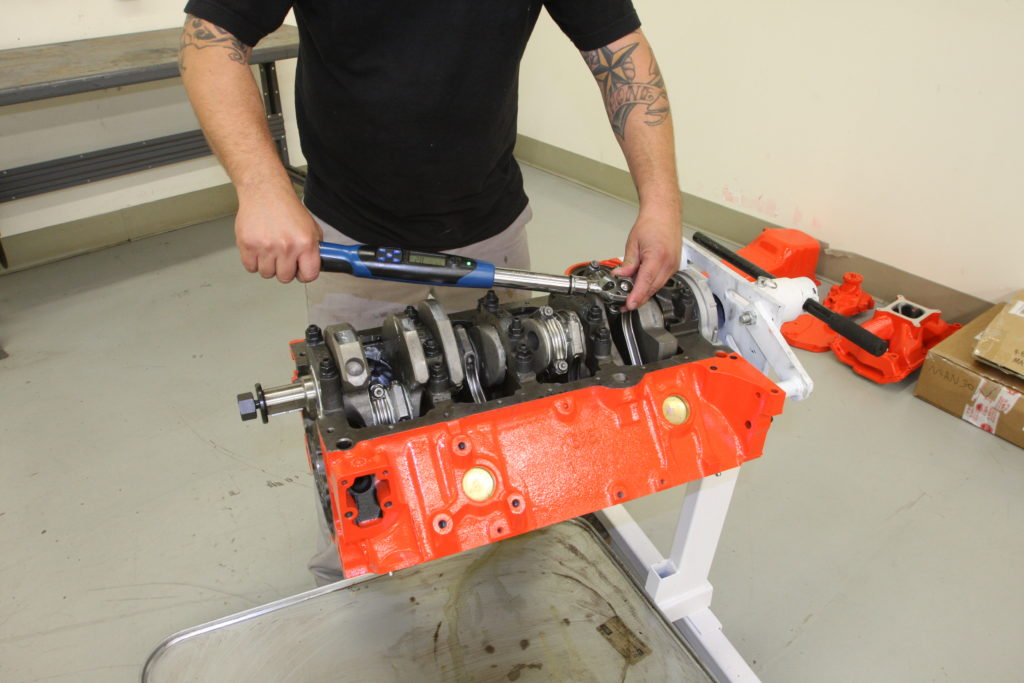
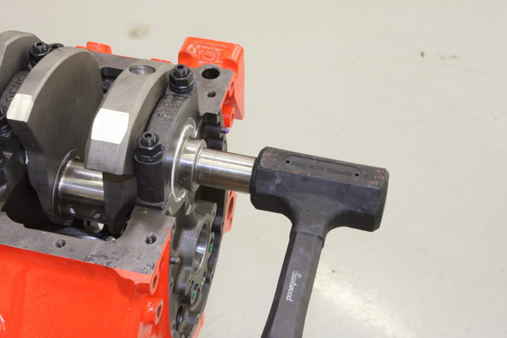
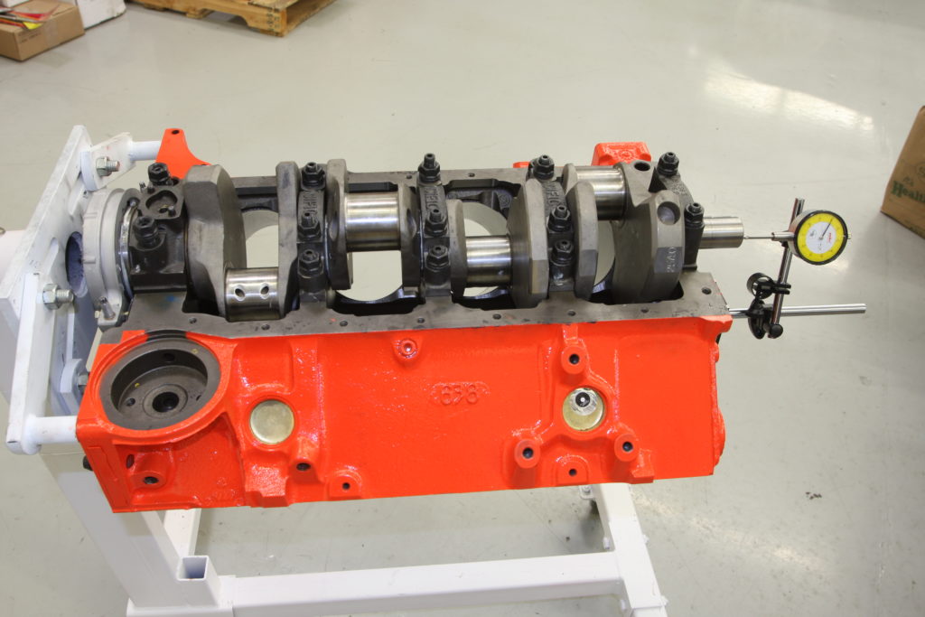
Here, the traditional method of measuring bearing clearances using Plastigage is shown. This crank/bearing assembly yielded an acceptable 0.002-inch clearance, noted by comparing the crushed wire to the provided chart. Using the more technical method, first we measure the crank journals using a micrometer.We’ll be using a dial bore gauge to check the tolerances of both the main bearings as well as the rod bearings when we get to the rotating assembly. Powerhouse Products makes this example, which can measure diameters from 1.4- to 6-inches by swapping out the various anvils and indicating spacers. We’ll be using a 2.6-inch anvil in the bore gauge to measure the crank bearing clearances. With the micrometer installed in a small vise, the dial bore gauge is zeroed to the crank journal’s size.Next, the dial bore gauge is used to measure the diameter of the main bearing assembly. Here, we’re measuring the assembly as machined with the stock main cap bolts torqued and the main bearings in place.We’re going to supercharge our engine, so we opted to install a set of ARP main cap studs to keep the crank in the block. These are screwed into the block hand tight using ARP assembly lube. By installing them hand tight, it ensures that the force is exerted upon the entire threaded length of the fastener. If the studs were to be inserted fully and tightened down snug, the force may not be applied evenly and failure could be an issue. Though our block was align honed, it was done so using the stock main cap bolts. Since the clamping forces can change when swapping out cap bolts for studs, it’s necessary to check the tolerances with the main studs installed and torqued to spec, then compare them to the tolerances witnessed on the original assembly. The two should be the same. If not, another align hone with the studs installed may be necessary.Notice the difference between the dial bore gauge’s reading and the zero mark? That’s our bearing clearance; 0.0025-inch. Exactly where we want it to be so no additional machining is necessary. With the bottom end checking out, we can now install the crank, but not before it receives a thorough cleaning in the parts washer. Next, a layer of Comp Cams Assembly Lube is applied to the upper bearing shells. Our Eagle kit came with King XP High Performance Engine Bearings which are designed to meet the demand for higher bearing load capacity found in higher horsepower engines.The crank is then gently set in place. The main caps are then installed with the corresponding, lubed up, bearing shell in place. A gentle tap of a rubber mallet ensures that the cap is firmly seated before fastened in place. Damage to the block or main cap can occur if a main cap is fastened before it’s properly seated. This is the one-piece rear main seal housing that bolts to the back of the block and keeps oil from leaking through the rear main bearing (like every old small block seems to do!). With the crank in place, this can be slid over the crank flange and installed. Note that this housing will need to be purchased separately and is available from Summit Racing (#NAL-14088556).With the crank in place, it’s time to torque the main bearing caps. ARP recommends torqueing their fasteners in three equal steps, resulting in a final torque rating of 80 ft. lbs. The front four main caps are torqued, while the rearmost main cap is left snug so that we can check the crankshaft endplay clearance.This is controlled via the flanged surface of the rear main bearing in a small block Chevy which corresponds to a similar surface on the crankshaft. A thin layer of oil separates the two surfaces under normal operating conditions, allowing the crankshaft to travel fore and aft ever so slightly. First, the two bearing halves need to be aligned so that their two flanges are flush. This is accomplished by lightly tapping the crankshaft on the front snout and then on the rear crank flange. Failure to properly align the thrust bearing can result in total failure of the thrust bearing and catastrophic engine damage.With the rear main bearing properly seated, we can check the crankshaft end play. To do this, the crank is gently pried back and forth, taking notice of the amount of movement via a dial indicator that is mounted on the front of the block and resting against the snout of the crankshaft. For a high performance small block Chevy, ideal crankshaft endplay is between 0.002-0.006-inches. Our motor checked out at 0.005-inch, which is just right. If the endplay was found to be excessive, suspect a worn crank surface where it mates to the thrust bearing. A motor with excessive endplay or a thrust bearing failure can chew up the main bearings and the block due to the unrestrained forward thrust of the crankshaft. Unwarranted stress can also be applied to the connecting rods and wrist pins, which can lead to things that go “boom”. Not enough endplay can cause problems as well and can usually be ratified by carefully removing a few thou worth of material from the thrust surface on the bearing.
Related posts:
383ci SBC Build, part II Building a Bullet Proof Rotating Assembly 383ci SBC Build, Part II By Ryan Manson * clampdowncomp@gmail.com With the foundation of our 383ci Chevy build in place thanks to the installation of the forged Eagle 3 ¾-inch stroked crankshaft, it’s time to move onto the rotating assembly. That means it’s time...
383 SBC Build, Part III Installing the top end of our 383 blower build 383ci SBC Build, Part III By Ryan Manson * clampdowncomp@gmail.com With the short block assembled for our 383 supercharged project motor, it’s time to shift our attention once again; this time to the heads and valve train. Like the rotating assembly,...
Adding an oil fill tube Adding a vintage oil fill tube to a modern intake We machine our new Edlebrock intake to accept an oil fill tube and look the vintage part! Back before PCV valves were standard lexicon among hot rodders, venting a motor was oftentimes a simple matter of letting the crankcase vent...
383 SBC Build, Part IV Dressing up a modern engine with vintage amenities 383 SBC Build, Part IV By Ryan Manson * clampdowncomp@gmail.com It’s pretty exciting when your engine project starts coming together and you’ve finally got an assembled long block on your engine stand. For me, it’s usually the culmination of months of planning...
383 SBC Build, Part V Blowing the Build 383 SBC Build, Part V: A Prototype Never Produced- Chevrolet’s “Super-Fire V8” By Ryan Manson * clampdowncomp@gmail.com Here’s the valve-in-head V8 as only the leader can build it and here are some wonderful things it brings you: 578 horsepower and 620 lb-ft. torque made possible by the...
Adding a High Hump Tunnel to a Low Hump C10 Hump Day Making Room in a ’67-72 C10 For More Gears When the time came to really start thinking about dropping the LS/T56 combo into my ’68, the only thing that really concerned me was the clearance issue that might arise due to the low hump pan on the cab’s...