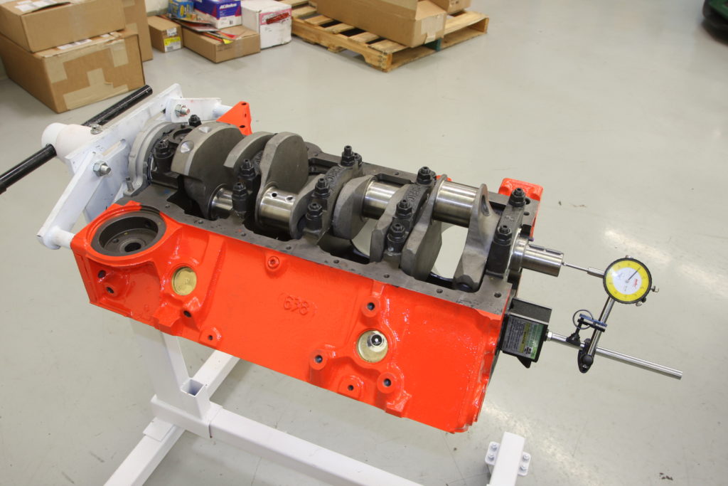
With the foundation of our 383ci Chevy build in place thanks to the installation of the forged Eagle 3 ¾-inch stroked crankshaft, it’s time to move onto the rotating assembly. That means it’s time to file the rings, unwrap the Mahle forged pistons and Eagle ESP rods before dropping in each piston assembly. Like when we installed the crank, we’ll also be checking the bore measurements, as well as the piston to wall, rod bearing, and connecting rod side clearance. Since we’re using a rotating assembly that is perfectly matched to the specs of our Summit Racing machined block, there shouldn’t be any surprises that arise when it comes to the rotating assembly, but it’s a good idea to check just in case as any mistake at this point could prove costly once the engine is fired up on the engine dyno.
With everything checked out, we were off and running, dropping hunks of aluminum and steel in the bores of our block. This is the point where engine building starts to get exciting as the whole assembly really comes to life with every turn of the crank. This is also the point where any overlooked detail can rear its ugly head, so care must be taken to achieve the proper clearances and ring end gaps prior to assembly. Thankfully, Summit Racing has gone above and beyond to ensure that even the most rudimentary engine builder (me!) can assemble an engine without the aid of an IndyCar Crew Chief. CC
Sources:
Automotive Racing Products, Inc (ARP) (800) 826-3045 www.arp-bolts.com
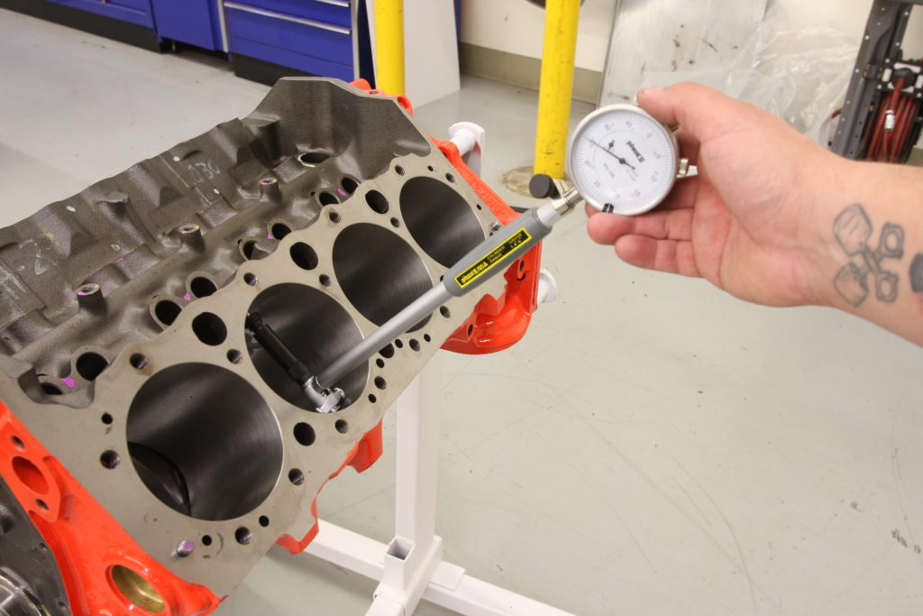
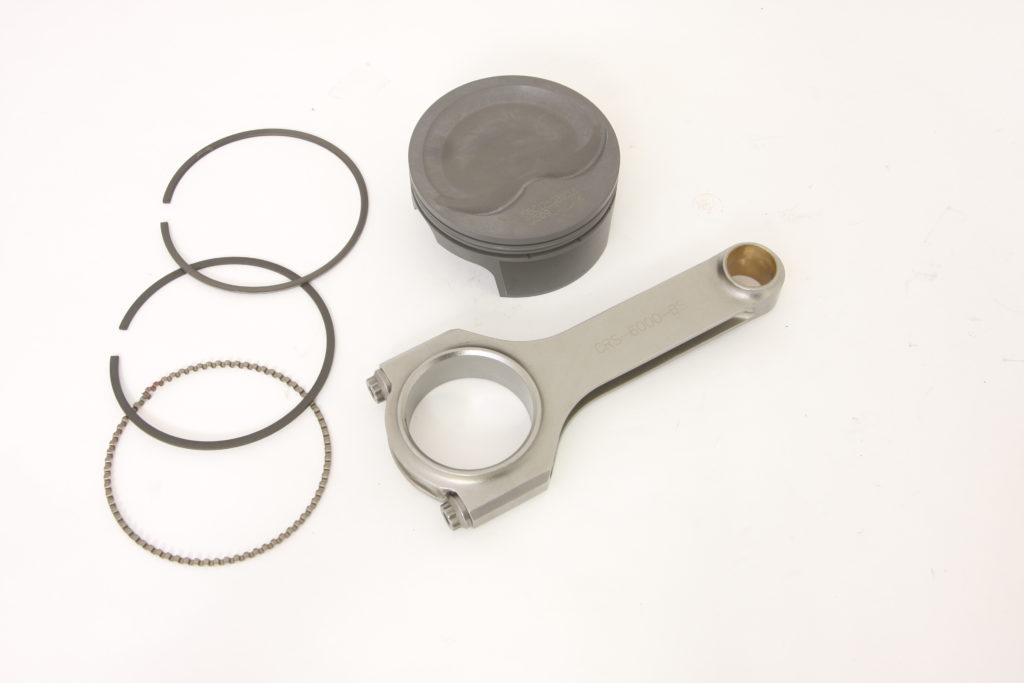
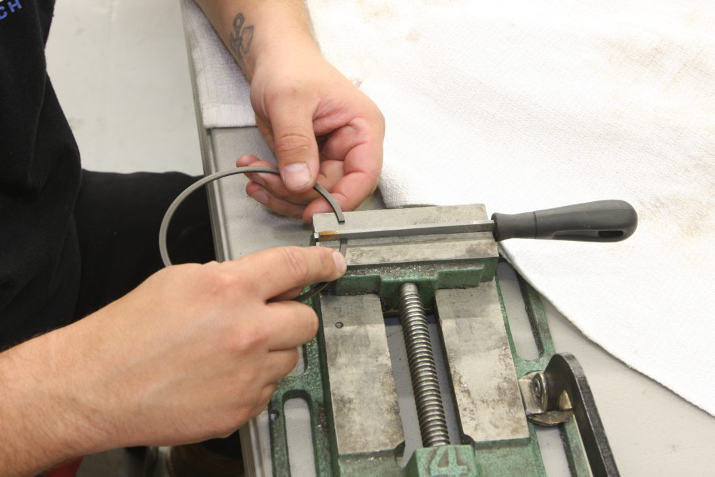
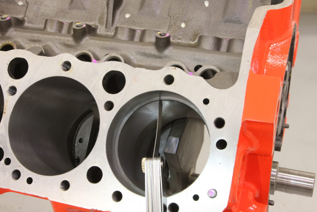
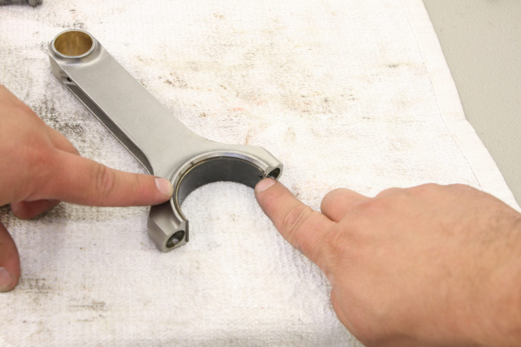
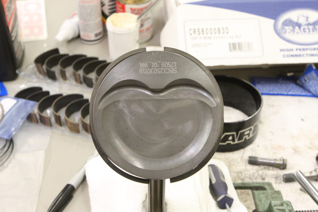
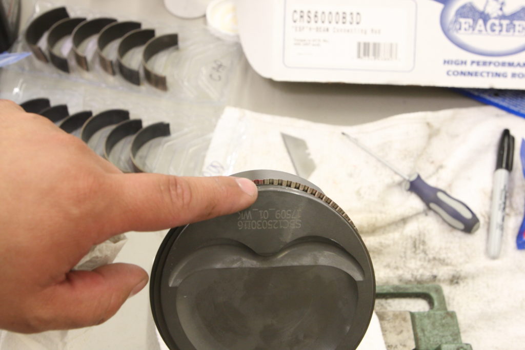
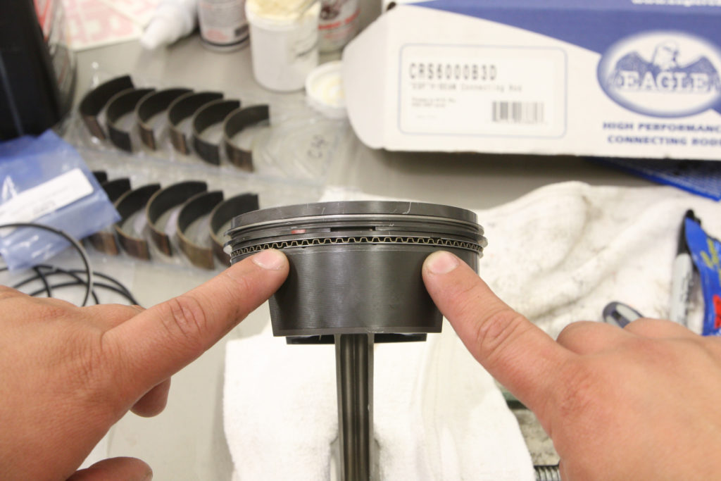
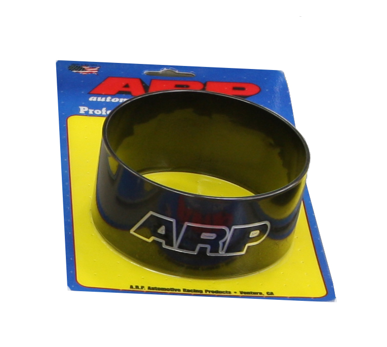
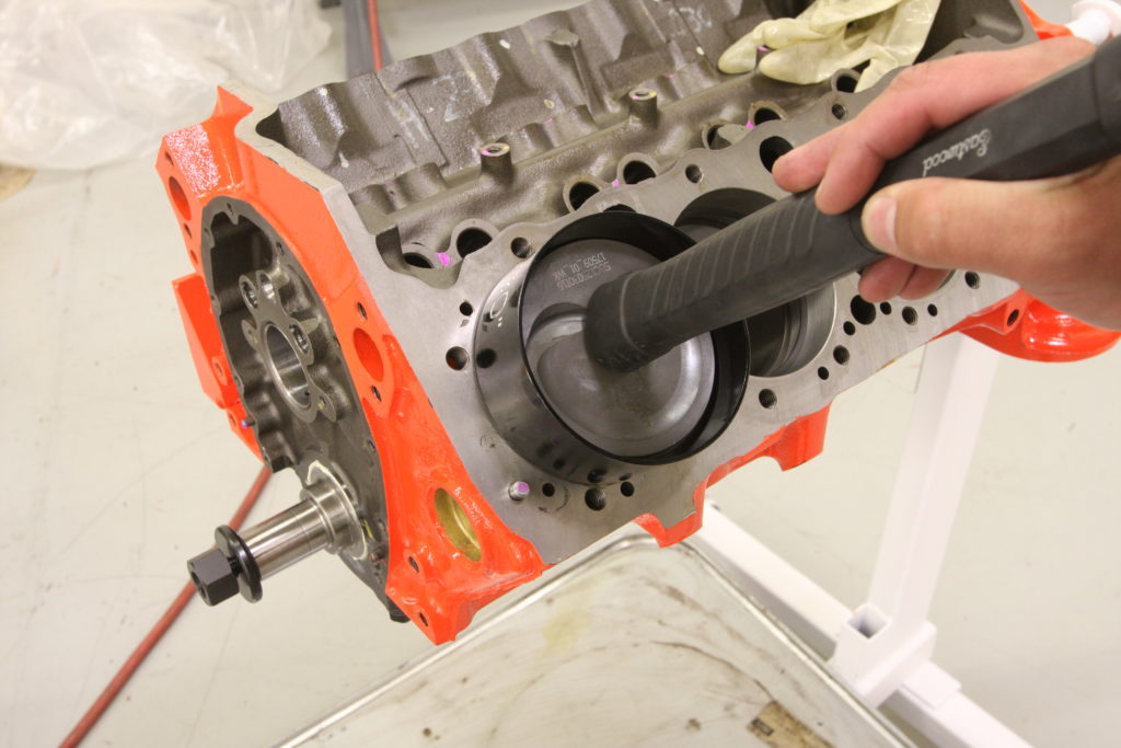
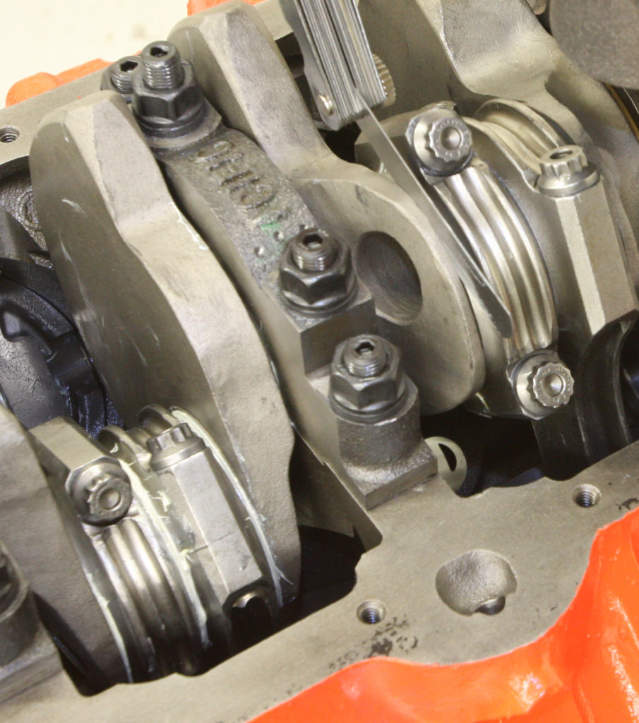
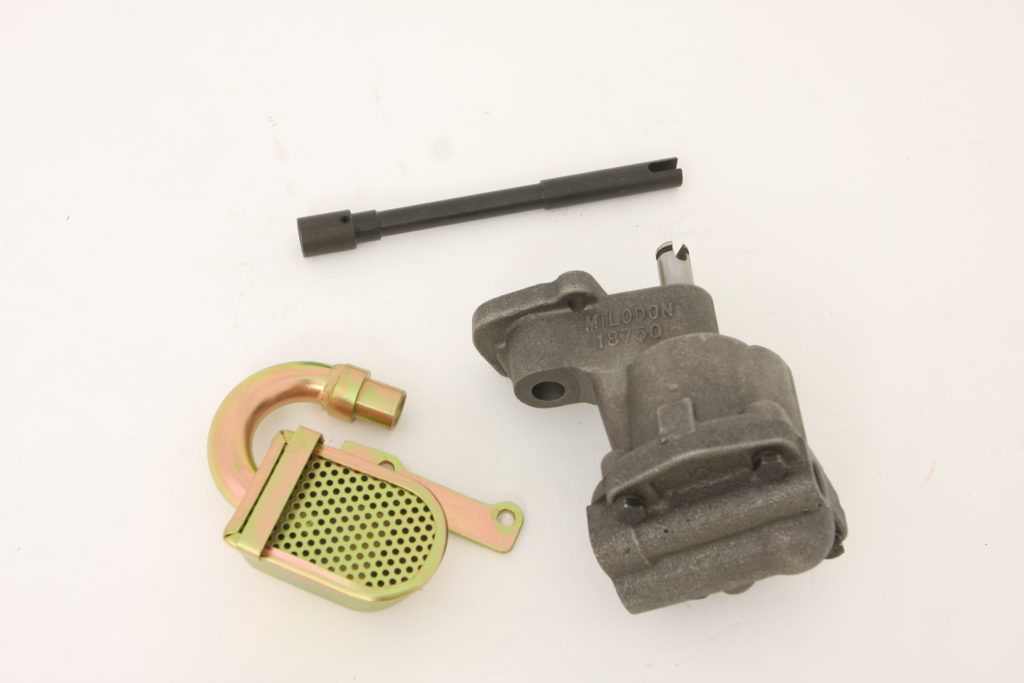
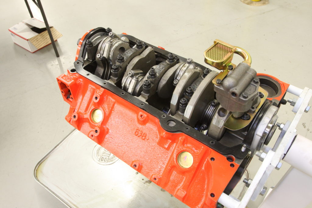
The specs on our block were double checked once again for good measure before dropping the pistons in place. Using the same process that we used to check the bearing clearances, first each piston is measured, then the bore is measured and the difference noted; this is our piston to cylinder clearance. For our application, it should be between 0.002-0.003-inch as measured 1/4-inch from the bottom of the piston skirt. As mentioned when we covered the bottom end build, we sourced the entire Eagle rotating assembly from Summit Racing, including the Mahle forged pistons, rings, and Eagle ESP H-beam rods. Piston pins and circlips as well as low-profile ARP 2000 rod bolts were also included in the kit. These pistons feature a -16cc inverted dome designed for a final compression ratio of 8.8:1 when combined with a 70cc cylinder head. This lower CR will allow us to put some boost into the engine without fear of detonation or having to run super high octane fuel.The Mahle performance rings included in our Summit Racing kit are of the file-to-fit variety. That means the top and second ring of every piston needs to be filed until the recommended end gap is achieved when compared to the cylinder bores in our engine block. For our application, that meant a ring gap of 0.020-inches for the top compression ring and 0.016-inches for the second. While there are a variety of ring gap filing machines out there, sometimes you just can’t beat the simplest method; a file mounted in a vise. Holding the ring nice and square against the file, the ring is carefully drug across the surface, slowly removing material and creating the necessary end gap.All of our rings were too large for the bore of our engine, so filing first and then checking the end gap as we progressed was the only way to make it happen. Working slowly and checking the gap often allowed us to maintain consistency and accuracy. When measuring the end gap, I used one of our Mahle pistons to push the ring squarely into the bore approximately one inch from the deck of the block. A feeler gauge was then used to determine the end gap.To ensure that each ring stayed with the cylinder which it was measured against, I left the rings in place as they were filed. Our Summit rotating assembly kit came with King Racing bearings, which we’re installing on the Eagle rods in order to check the rod bearing clearance, just like we did with the main bearings. Two things are worth noting when it comes to installing the rod bearings, and that’s the chamfer on the rod itself and the bearing tang that helps located and hold the bearing shell in place. With the rod bearing clearances checking out, it’s time to mate the pistons with the connecting rods. Our Mahle pistons utilize round wire locks to retain the piston pins, which can be a bit tricky to install at first. The most important thing is to not squeeze or compress the lock as this may compromise its spring tension, leading to failure. Instead, one end of the wire lock is placed in the piston groove while the lock is fully worked into the groove using a blunt tool. Once in place, a gentle tap using a wooden dowel against the pin will help ensure proper seating of the lock. Note that a light coating of assembly lube was used to help promote lubrication upon initial start up.Now it’s time to install the rings, starting with the bottom oil ring rail. Alignment of the ring gaps is important to reduce the possibility of blow-by and lost compression. Here, the top compression rings are installed for illustration purposes, with their end gaps staggered 180-degrees apart. The oil ring expander’s gap range should fall in the same vicinity as the top compression ring’s gap……while the top and bottom oil ring gaps should flank that of the bottom compression ring. At the end of the day, the goal is to provide the path of most resistance when it comes to any air, oil, or fuel getting past the rings. If you’ve ever wrestled with a junk piston installation tool, you know how frustrating it can be trying to stuff a three-ringed piston into its bore. Been there, done that, so when it came time to start dropping in the slugs, I opted to use ARP’s Tapered Ring Compressor to ensure that every piston dropped safely into the engine block without snagging any rings.ARP’s piston installation tools are bore specific, so be sure to get the corresponding size for your application; 4.030-inches for this build. Simply check the ring gaps one last time before applying a light coating of engine oil to the piston, then the assembly is slowly dropped into place. A light tap of a rubber mallet should be all that’s necessary to drive it home. Be sure to orientate the piston in accordance to any valve clearancing that’s machined into the top of the piston as well as the aforementioned chamfer on the bottom of the connecting rod as this meshes with a similar chamfer on the crank. Care must be taken when dropping each connecting rod/piston assembly into the engine so as to not damage the crank journals. If our con rods were equipped with studs, we could have used a set of ARP Rod Bolt Extensions to ease installation even further. Working from the front of the engine, each assembly is installed with one half of the rod bearing in place, followed by the cap and corresponding bearing half. Following an initial torque of 35 ft lbs, the crank is the spun to ensure that the new, added assembly is not problematic. If everything checks out, the rod bolts are then torqued to their final setting of 75 ft lbs and the assembly spun and checked out again. This process is repeated until all eight cylinders are filled with forged aluminum slugs.The last thing to check before our rotating assembly is sorted is the connecting rod side clearance. Measured on either side of every connecting rod using a feeler gauge, the clearance should be in the neighborhood of 0.010-0.020-inch. To provide plenty of lubrication to the small block’s internal components, I’ll be using a high-volume, high-pressure Milodon pump (#MIL-18750), sourced from Summit Racing, mated to a Milodon 18307 pickup. An ARP oil pump driveshaft (#134-7901) kit will mate the pump to the distributor. A corresponding Milodon oil pan (#31501) will also be used, which features a 5-quart capacity and windage tray to help contain the oil supply. Milodon’s one-piece oil pan gasket is a huge improvement over the older four-piece gaskets and once you use one, you won’t go back. Installing the pickup in the pump body is pretty straightforward but can be easily botched if care is not exercised. For starters, the pickup should easily press into the pump housing. Placing the pickup in the freezer for a few hours will allow it to shrink sufficiently so that it can be installed by hand. Once fully home, the two retaining fasteners can be snugged up, held in place indefinitely by a drop of Loc-Tite. Next, the ARP oil pump driveshaft is dropped into the block, followed by the oil pump assembly. At this point, it’s important to check for clearance against the installed assembly and the depth of the oil pan; 1/4-3/8-inch is recommended. At this point, our bottom end is ready to be covered up for good!
Related posts:
383 SBC Build, Part IV Dressing up a modern engine with vintage amenities 383 SBC Build, Part IV By Ryan Manson * clampdowncomp@gmail.com It’s pretty exciting when your engine project starts coming together and you’ve finally got an assembled long block on your engine stand. For me, it’s usually the culmination of months of planning...
383 SBC Build, Part V Blowing the Build 383 SBC Build, Part V: A Prototype Never Produced- Chevrolet’s “Super-Fire V8” By Ryan Manson * clampdowncomp@gmail.com Here’s the valve-in-head V8 as only the leader can build it and here are some wonderful things it brings you: 578 horsepower and 620 lb-ft. torque made possible by the...
383 SBC Build, Part III Installing the top end of our 383 blower build 383ci SBC Build, Part III By Ryan Manson * clampdowncomp@gmail.com With the short block assembled for our 383 supercharged project motor, it’s time to shift our attention once again; this time to the heads and valve train. Like the rotating assembly,...
383ci SBC build, part I Bottom end basics for a blown small block Chevy engine build 383ci SBC Build, Part I By Ryan Manson * clampdowncomp@gmail.com When it comes to powering that project that you’ve been working on, there are basically three options; buying a crate engine, buying a junkyard motor, or building an engine...
Adding an oil fill tube Adding a vintage oil fill tube to a modern intake We machine our new Edlebrock intake to accept an oil fill tube and look the vintage part! Back before PCV valves were standard lexicon among hot rodders, venting a motor was oftentimes a simple matter of letting the crankcase vent...
Holley Terminator Stealth 2×4 We cover the basics of setting up a 2×4 Holley Terminator Stealth EFI System By Ryan Manson * clampdowncomp@gmail.com Sources: Holley (866) 464-6553 www.holley.com...