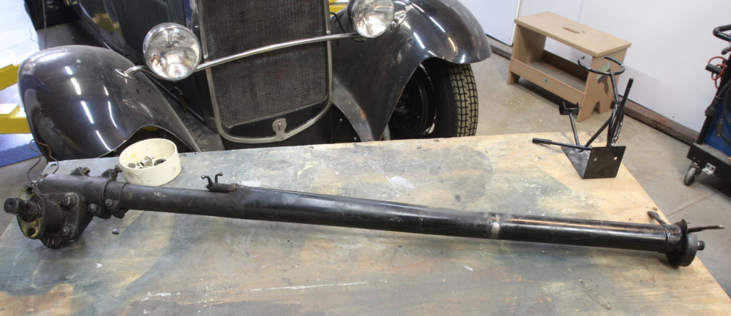
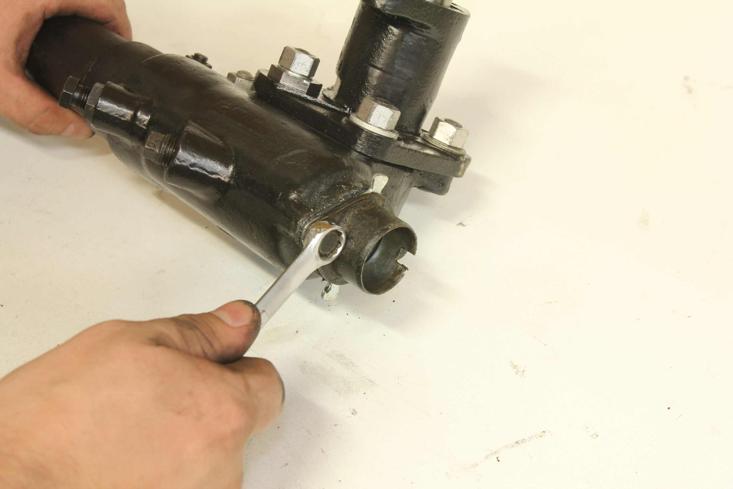
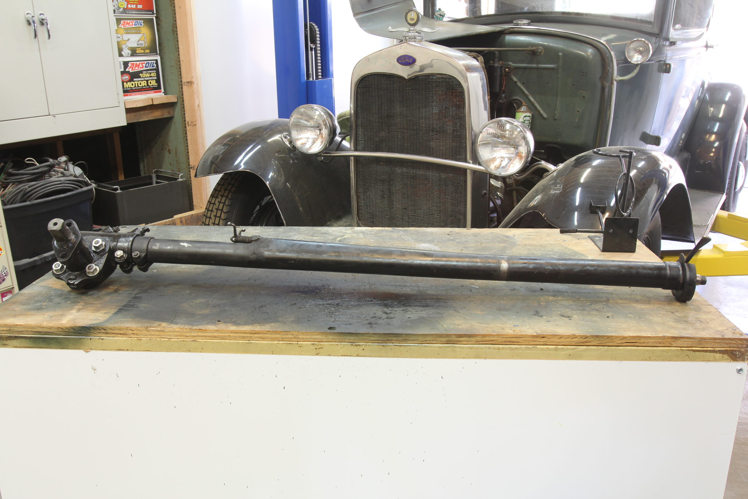
Here’s the stock steering box before we removed the column.
When it comes to owning a 90 year old car, one thing is for certain: there’s always going to be something to work on! That has been the case with our 1930 Ford Model A coupe since we purchased it a year or so ago. We rebuilt the carb, rebuilt the water pump, swapped the transmission and went through just about every other mechanical item of note trying to make things “safe and sound”. But after multiple attempts at adjusting the steering box, it either felt too sloppy or too tight, with no option in between. It was fast becoming obvious that it was time to pull the box out of the car for a proper rebuild.
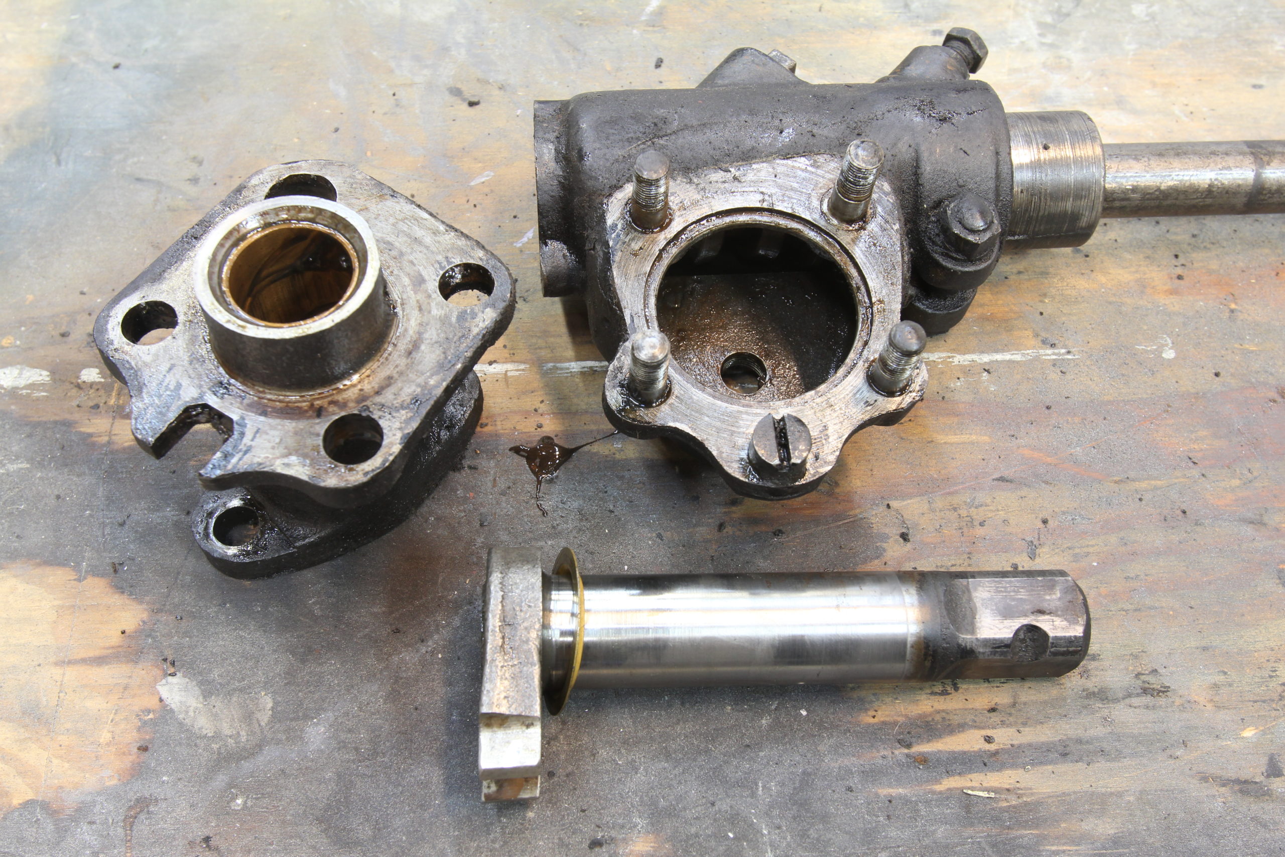
Thankfully, that task is rather simple after removing the floorboards (which we already had out) and pulling the starter. From there, it’s a matter of disassembling the box and inspecting for damage. Normally, damage isn’t something one wants to find. But when it comes to solving a mechanical problem like a tight steering box, not finding damage means not solving the problem. We want damage and we want to solve the problem. So, we tore into the box, pulled the sector housing and carefully inspected the bearings, races, worm gear, and sector, and came to the conclusion that there was some serious pitting on the bearing races, wear in the sector and worm gear, and zero oil in the box whatsoever. Damage? Check.
With a list of parts that neared “replace entire steering box”, we set off to CW Moss Ford Parts in Orange, California to grab all the new components needed to rebuild our steering box better than new. Hopefully, with the box back together and adjusted nice and snug, our Model A will drive just like Henry intended. CC
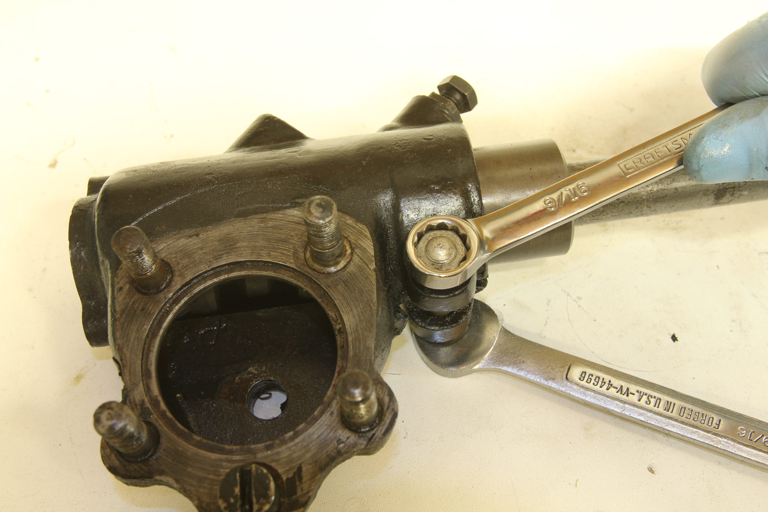
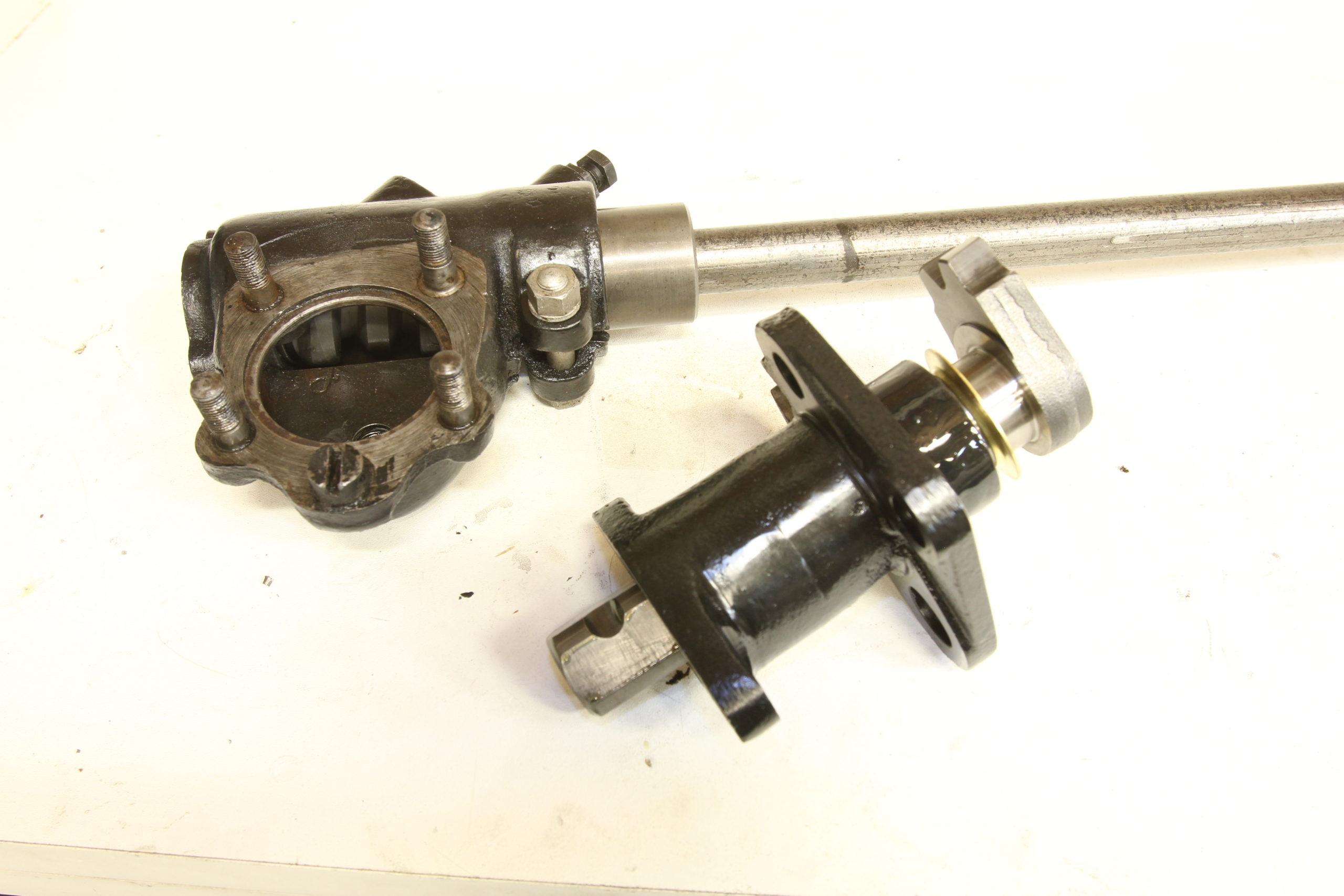
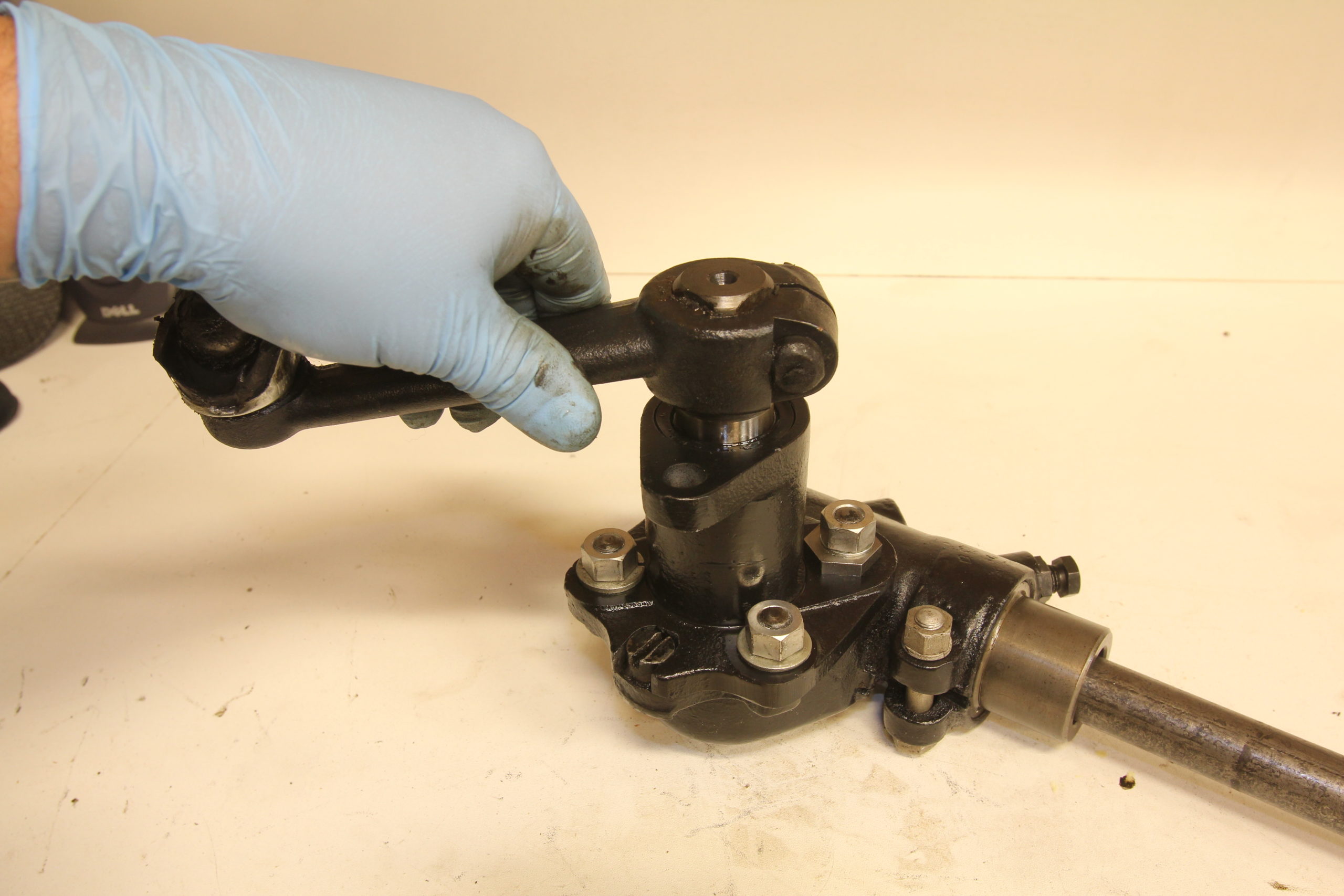
First up, splitting the sector housing from the main housing.
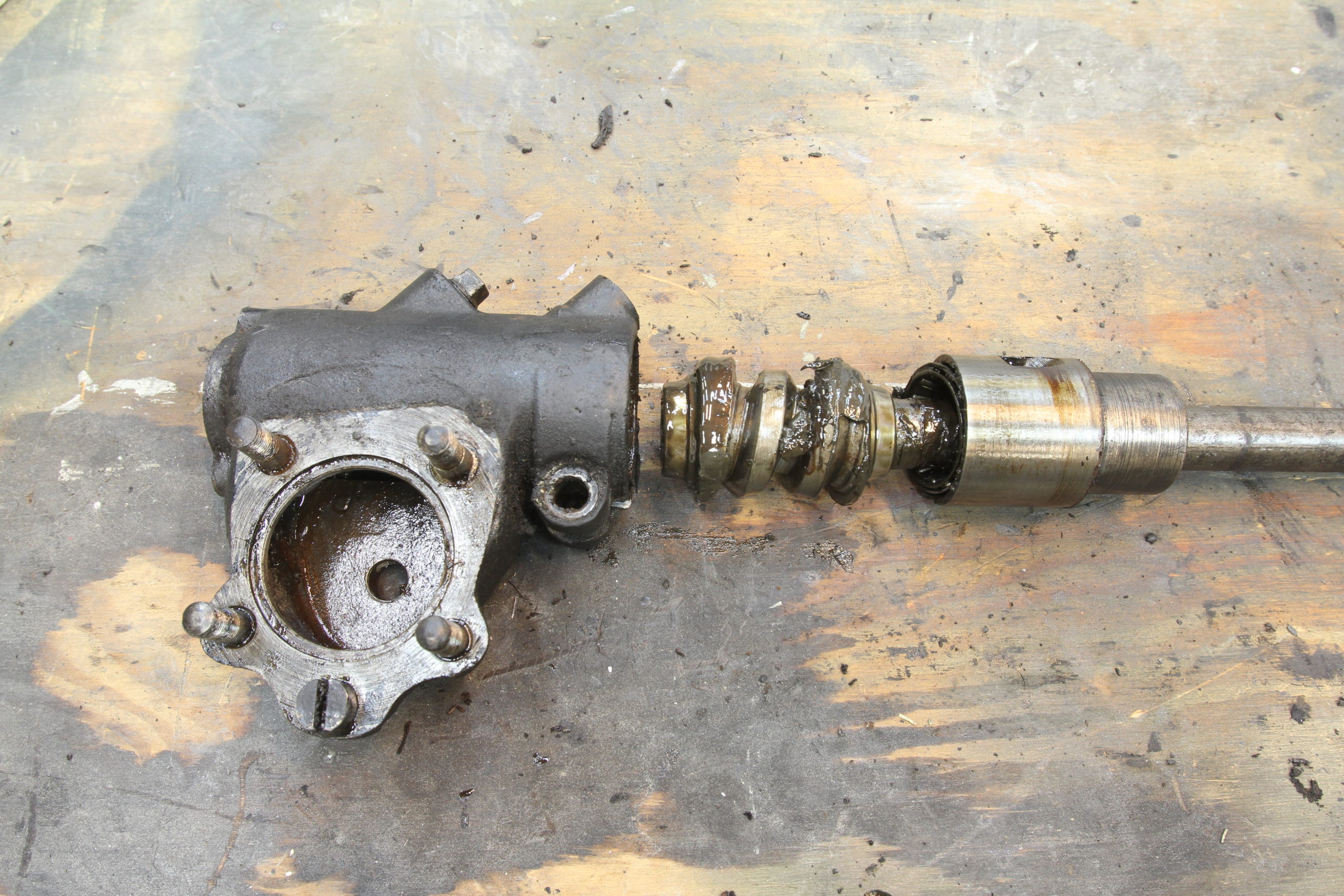
Next, the steering shaft can be removed.
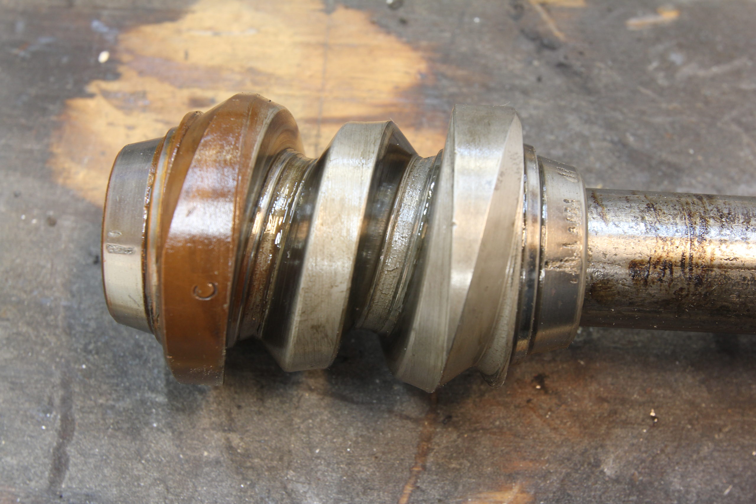
Pitting on the bearing surfaces of the worm gear are evident…
…as well as the surface of the upper race.
The two-tooth sector shaft also showed wear, which likely contributed to the slop we felt in the steering wheel.
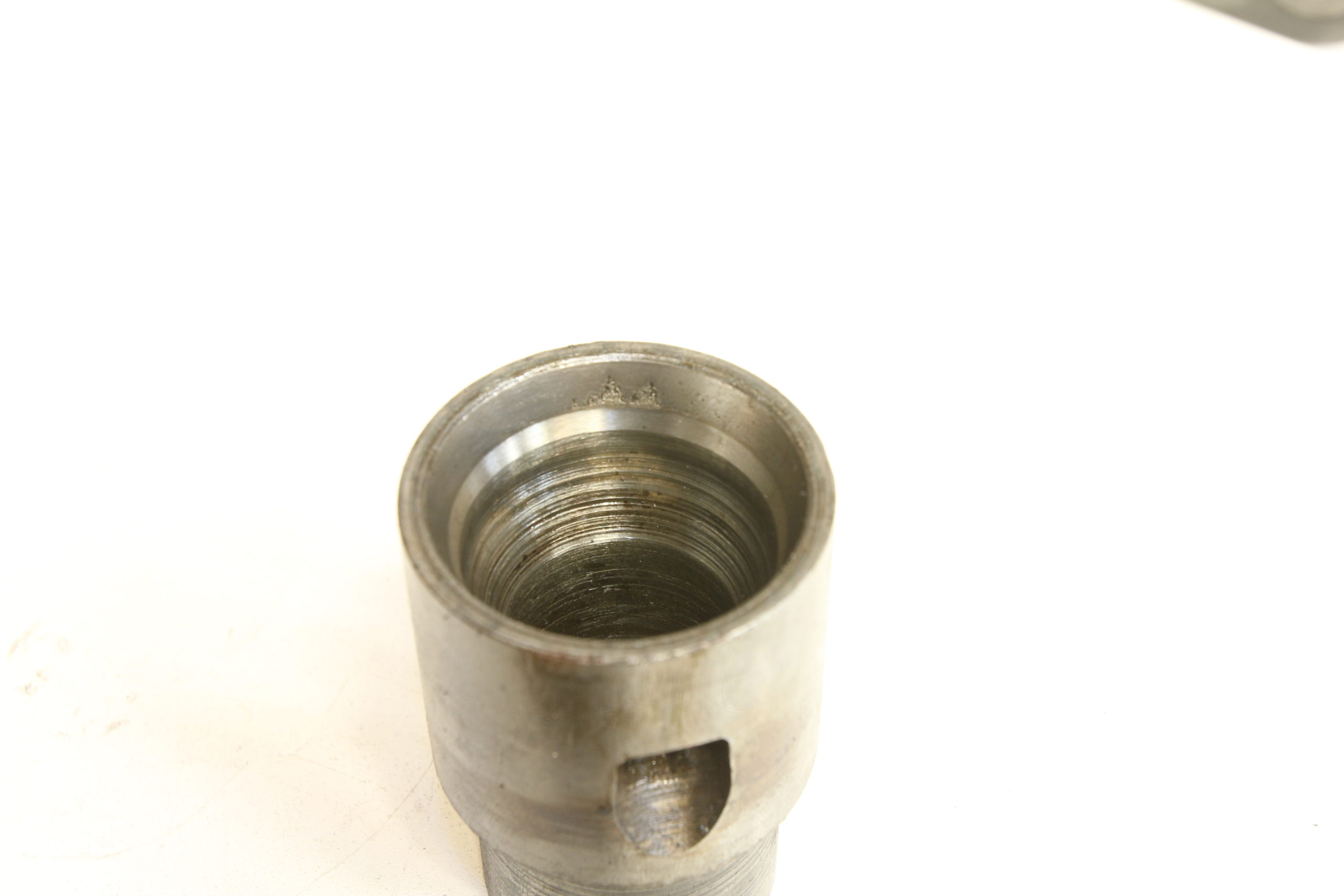
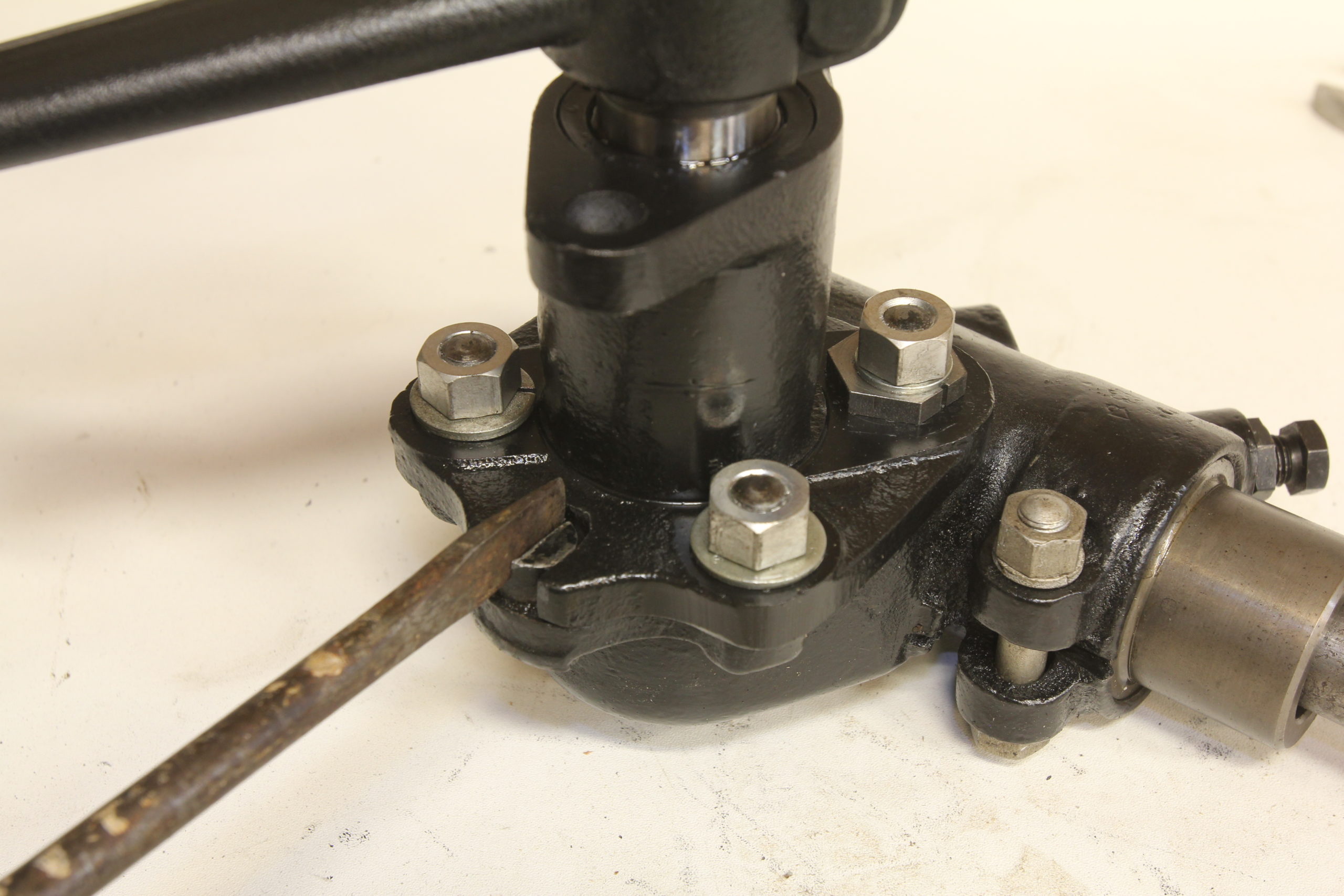
The lower race needs to be removed from the main housing using a drift inserted through the oil retaining tube mounting holes. Driving it out nice and square is the key.
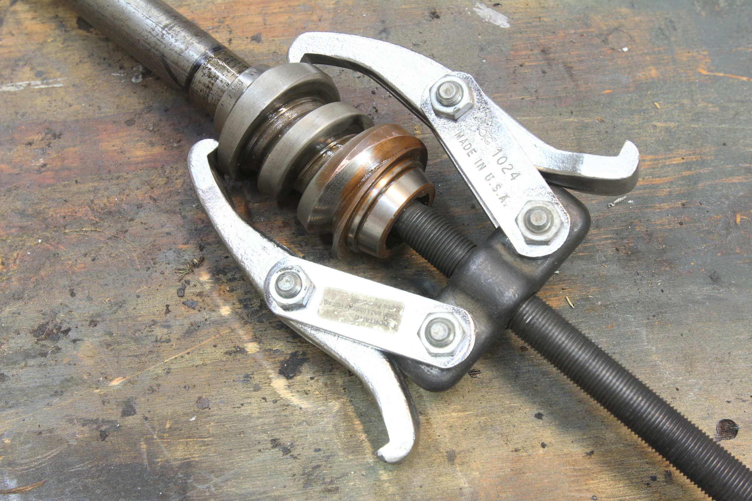
Pulling the worm gear from the steering shaft is easily achieved using a standard two-arm puller.
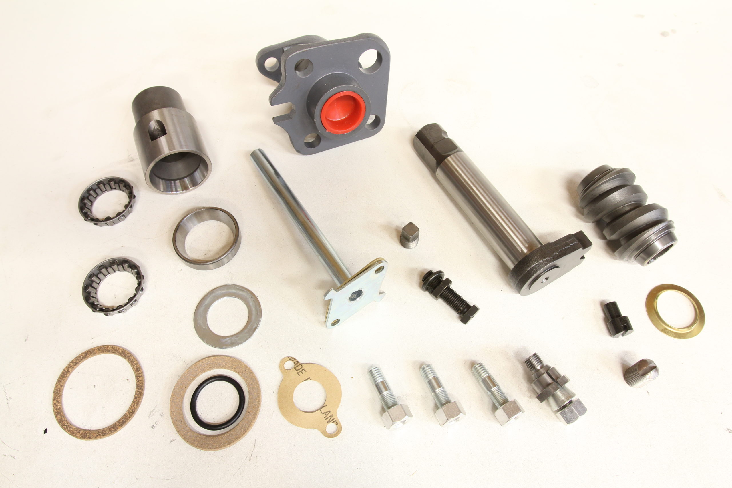
We ordered just about every new part CW Moss had available for the 2-tooth steering box including a new upper race, bearings, sector, worm gear, oil retaining tube, studs, nuts, adjusting cone, sector end play screw, steering shaft end play adjusting bolt, and one of the most important items that will hopefully make the biggest difference in our rebuild, a new sector housing with needle roller bearings.
The original Model A sector housing used solid rolled bronze bushings that were reamed to fit the sector shaft. Eventually, these bushings wear out, causing slop in the sector with the potential to leak oil out of the steering box. The new sector housing features roller needle bearings in place of the bushings, which shouldn’t wear, and a seal to prevent the heavy weight oil from leaking out of the box.
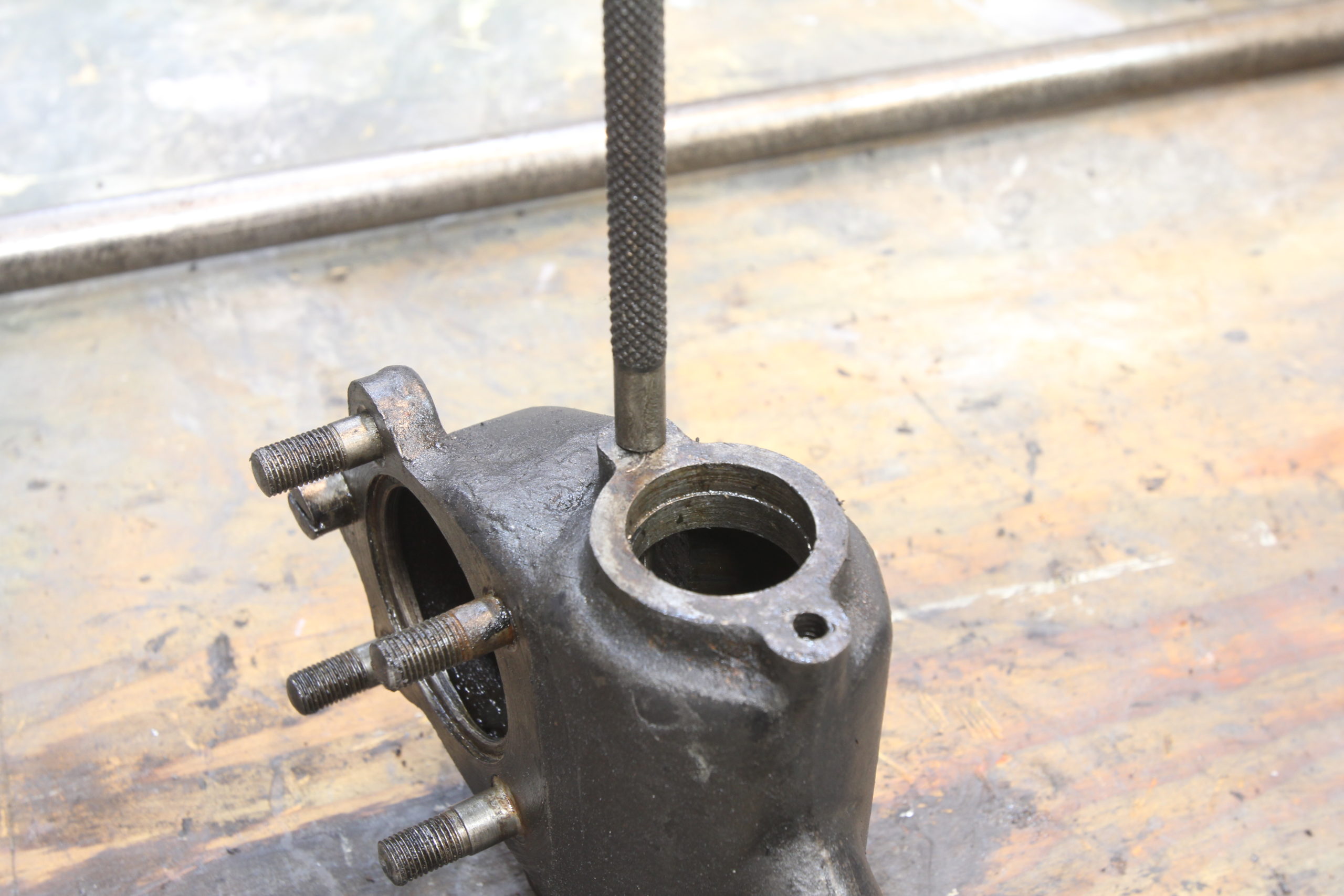
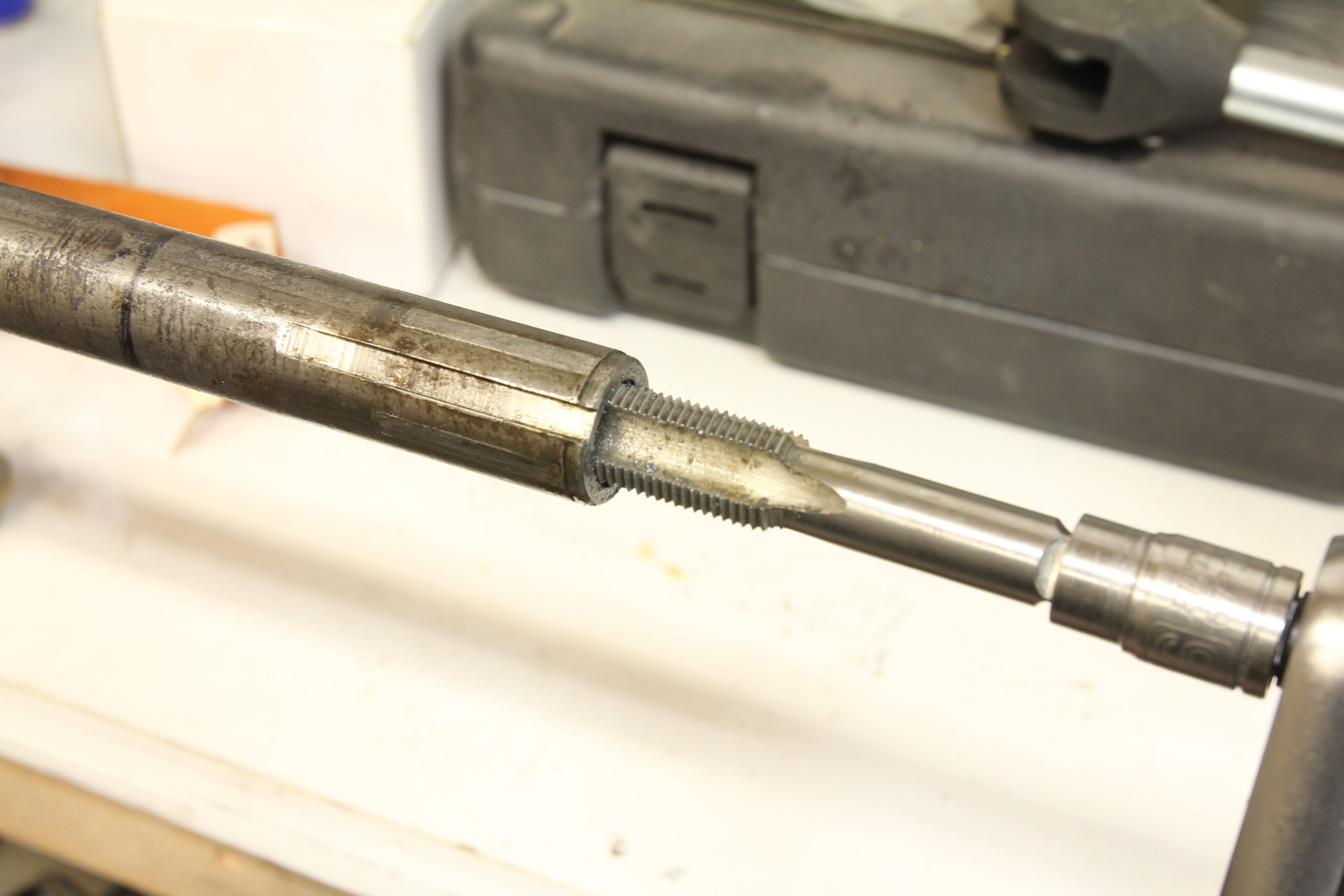
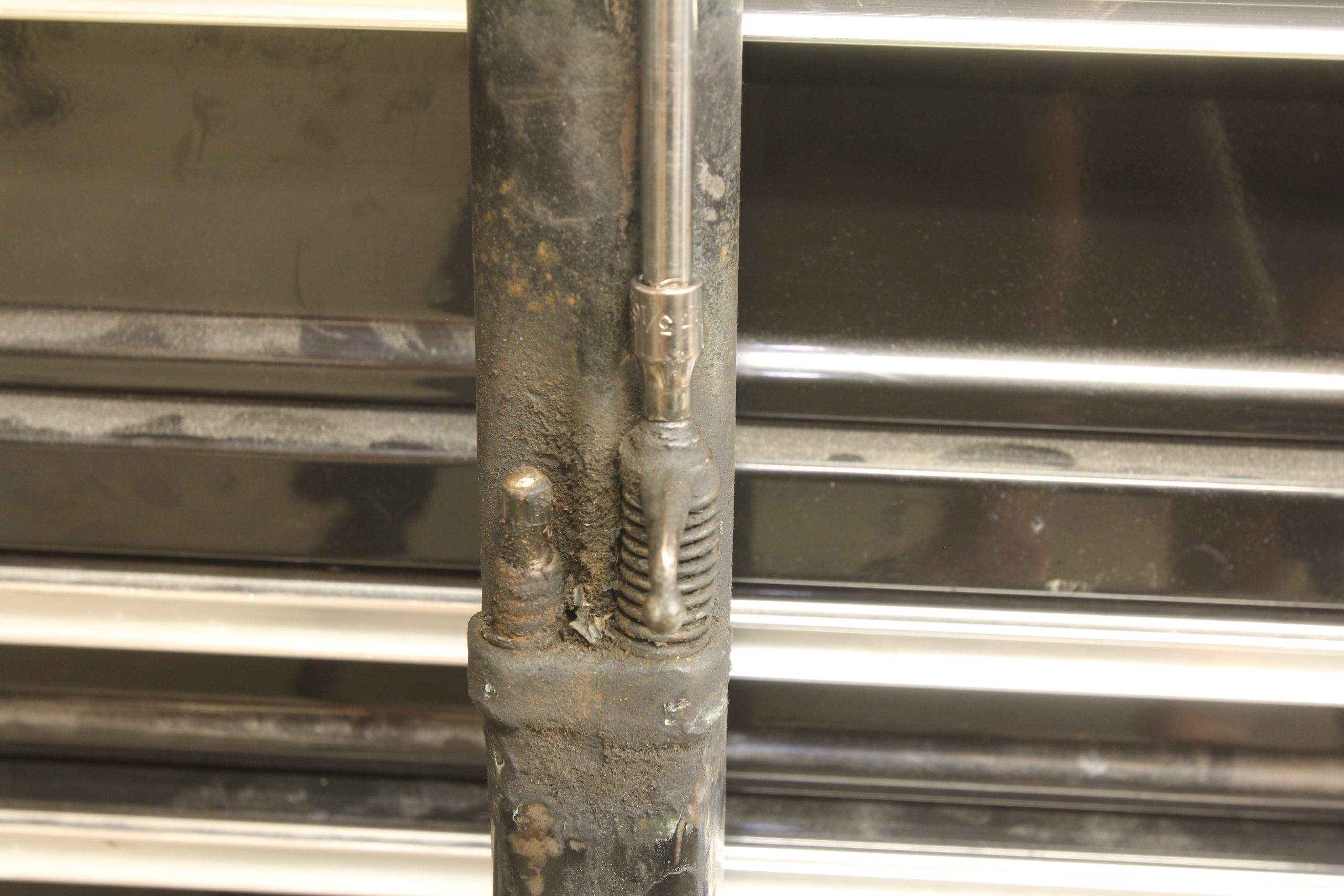
Pressing the new worm gear on the steering shaft can be problematic unless you have a really tall hydraulic press. Instead, we use a bit of ingenuity. By tapping the end of the steering shaft with a 5/8-18 tap…
…we can then use a corresponding bolt to drive the gear onto the shaft. Simple and effective.
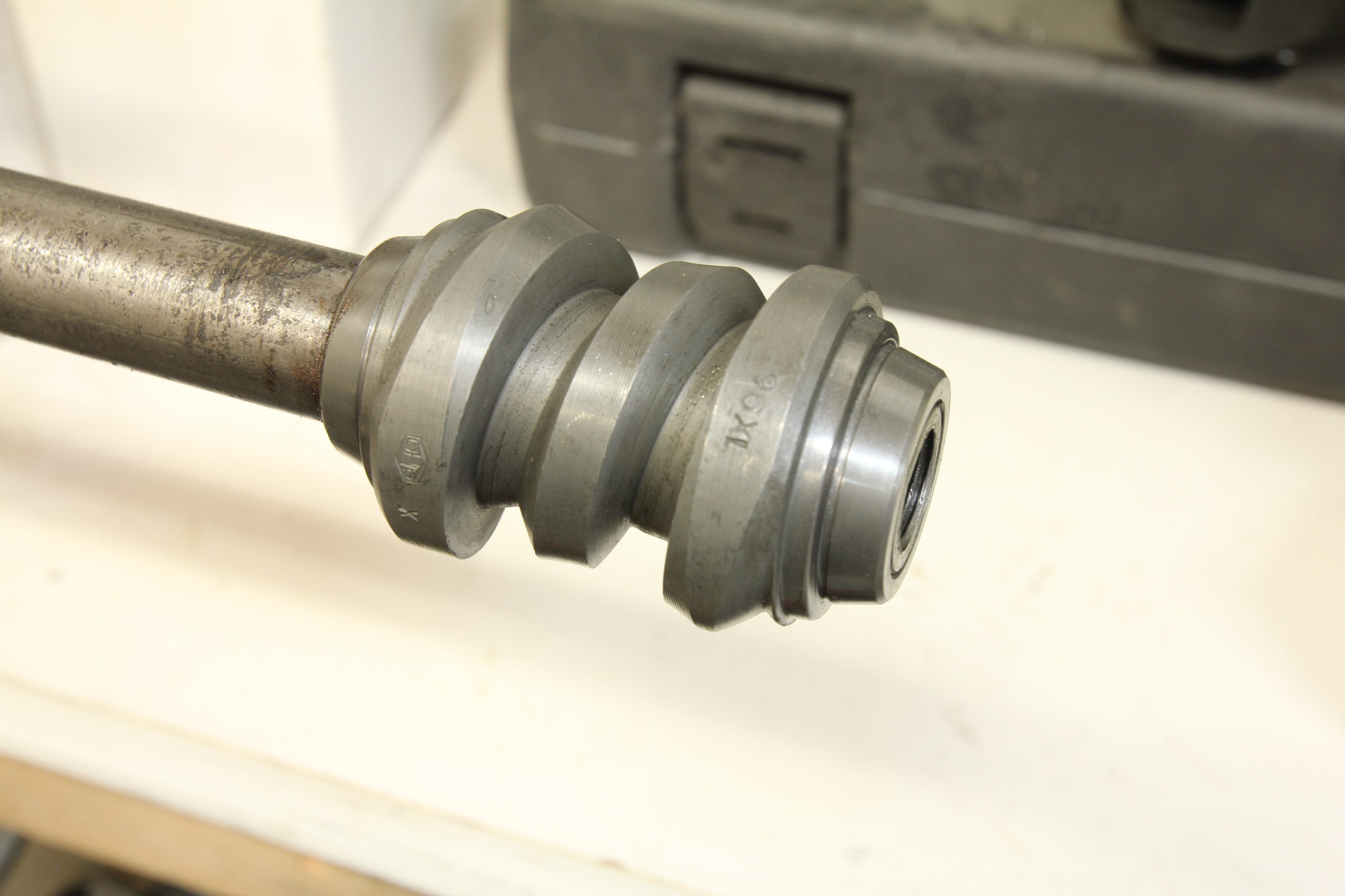
Here’s the new worm gear installed on our steering shaft. Note that it’s pressed on even with the bottom of the steering shaft.
With the worm gear installed, it’s time to start rebuilding our steering box. First, the lower race is installed, followed by the tapered bearing, worm gear, another tapered bearing, and the upper race. Be sure to line up the indention on the upper race with the steering box housing’s steering shaft end play bolt hole.
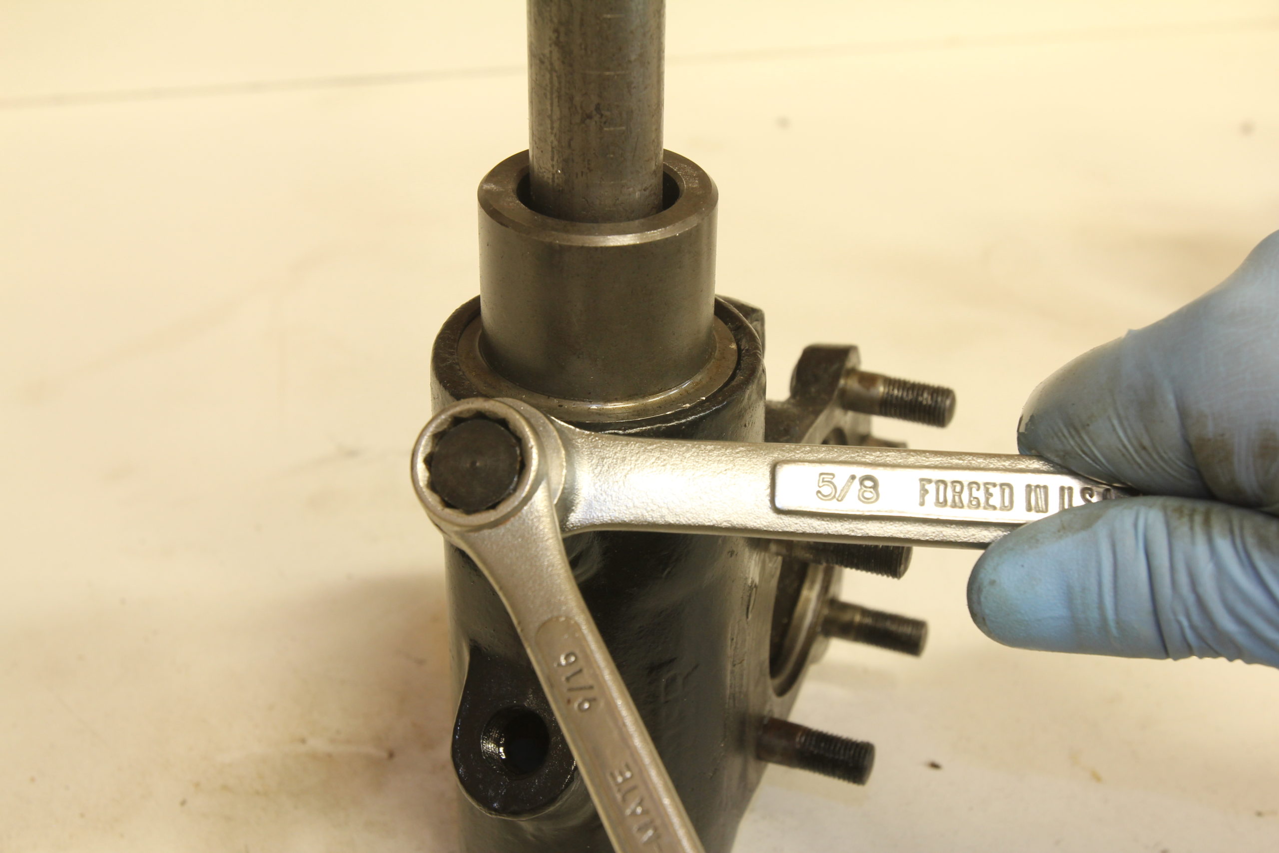
Next, the steering shaft end play is adjusted and locked down. The proper adjustment for the steering shaft end play is to tighten the end play bolt until there is zero end play detected by moving the steering shaft fore and aft, then the adjusting bolt is backed off 1/8 turn and locked down using the lock nut . Adjusting this bolt too tight can cause the upper race to crack!
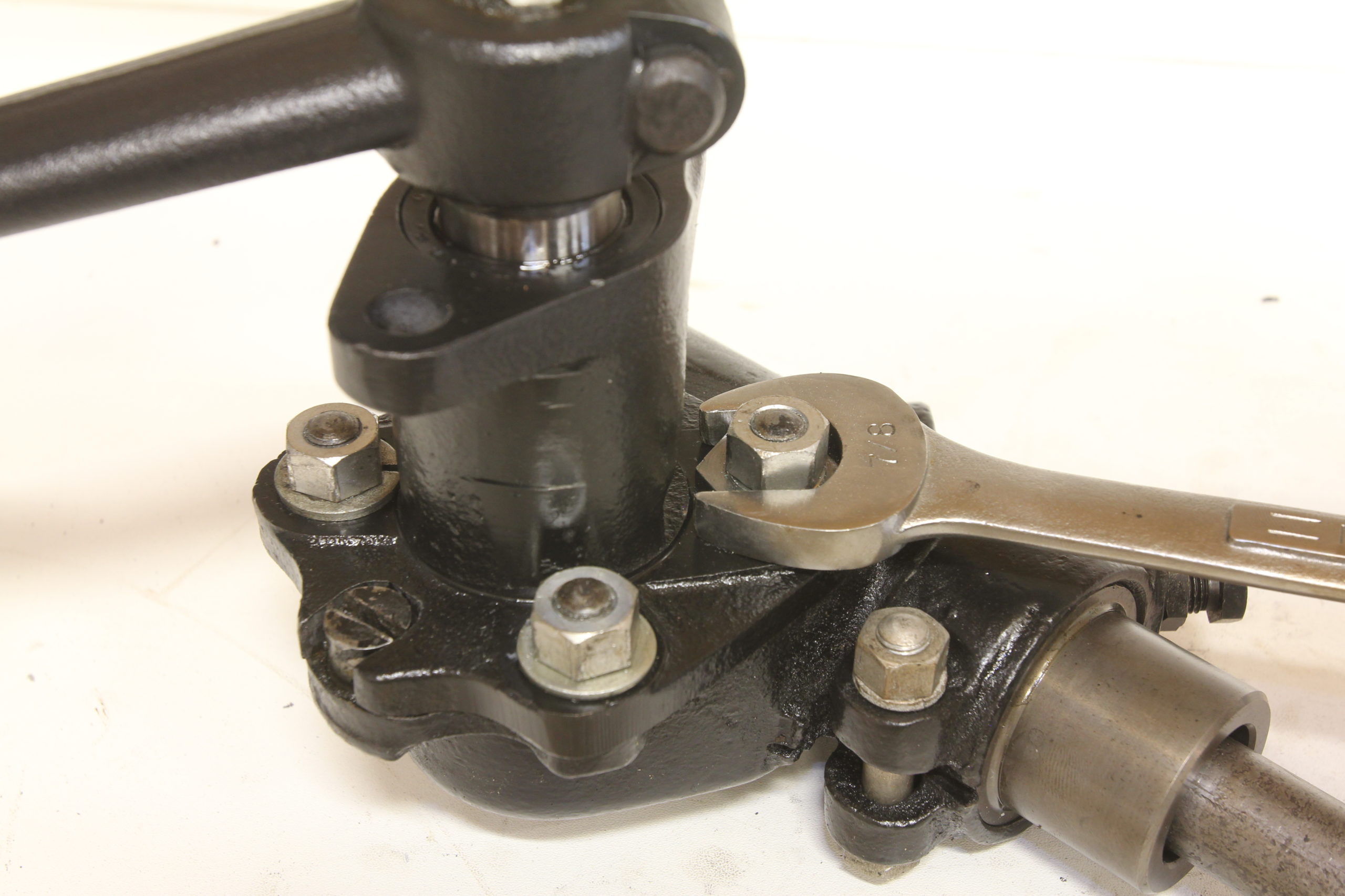
With the end play adjusted, it’s time to lock things down using the upper race retaining bolt.
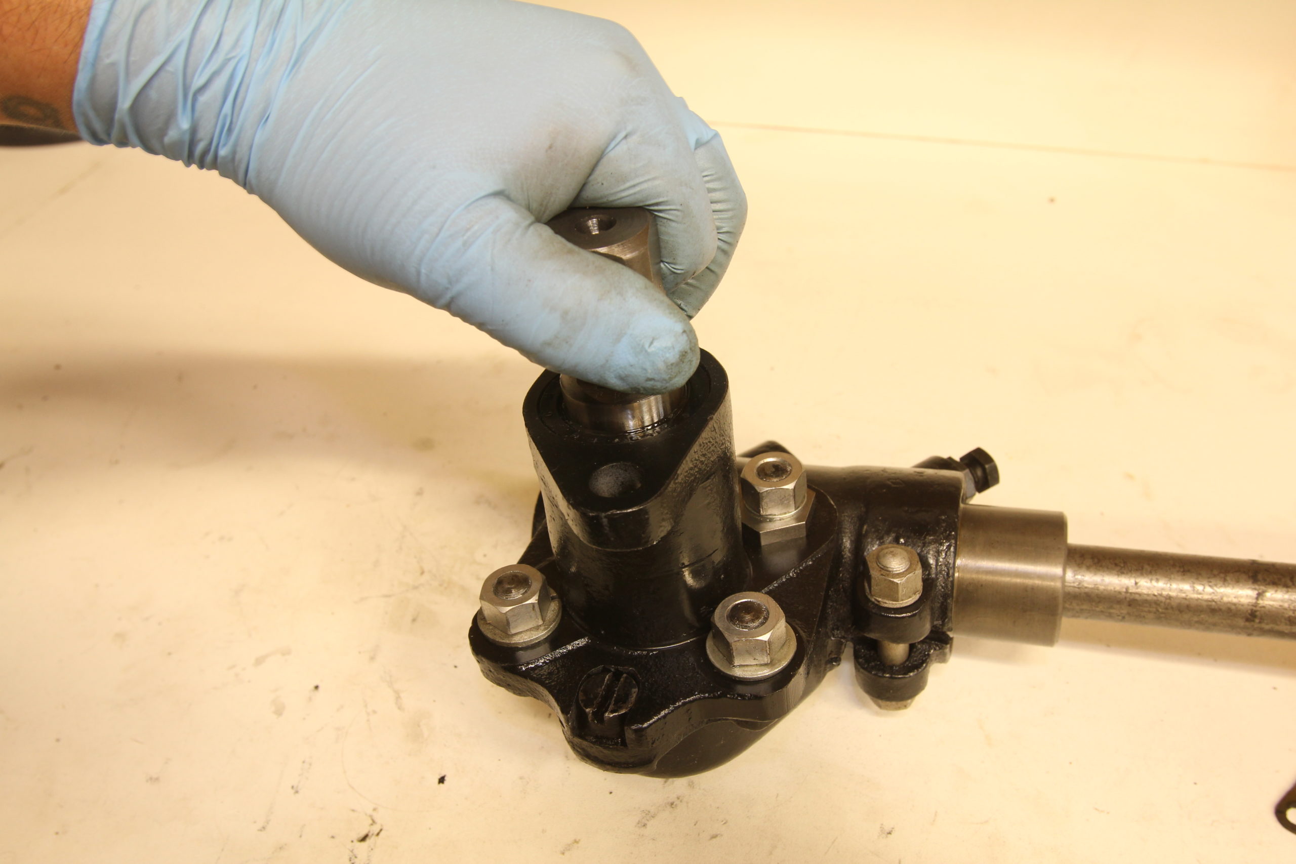
Before the sector housing and shaft are mated to the main housing, note the location of the brass thrust washer.
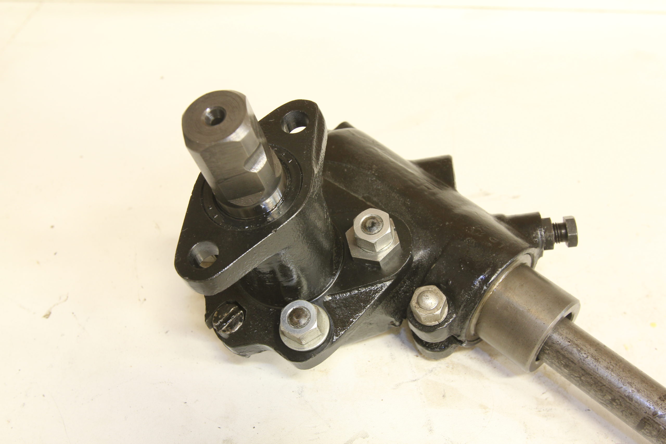
Here, the steering box is now assembled as one unit.
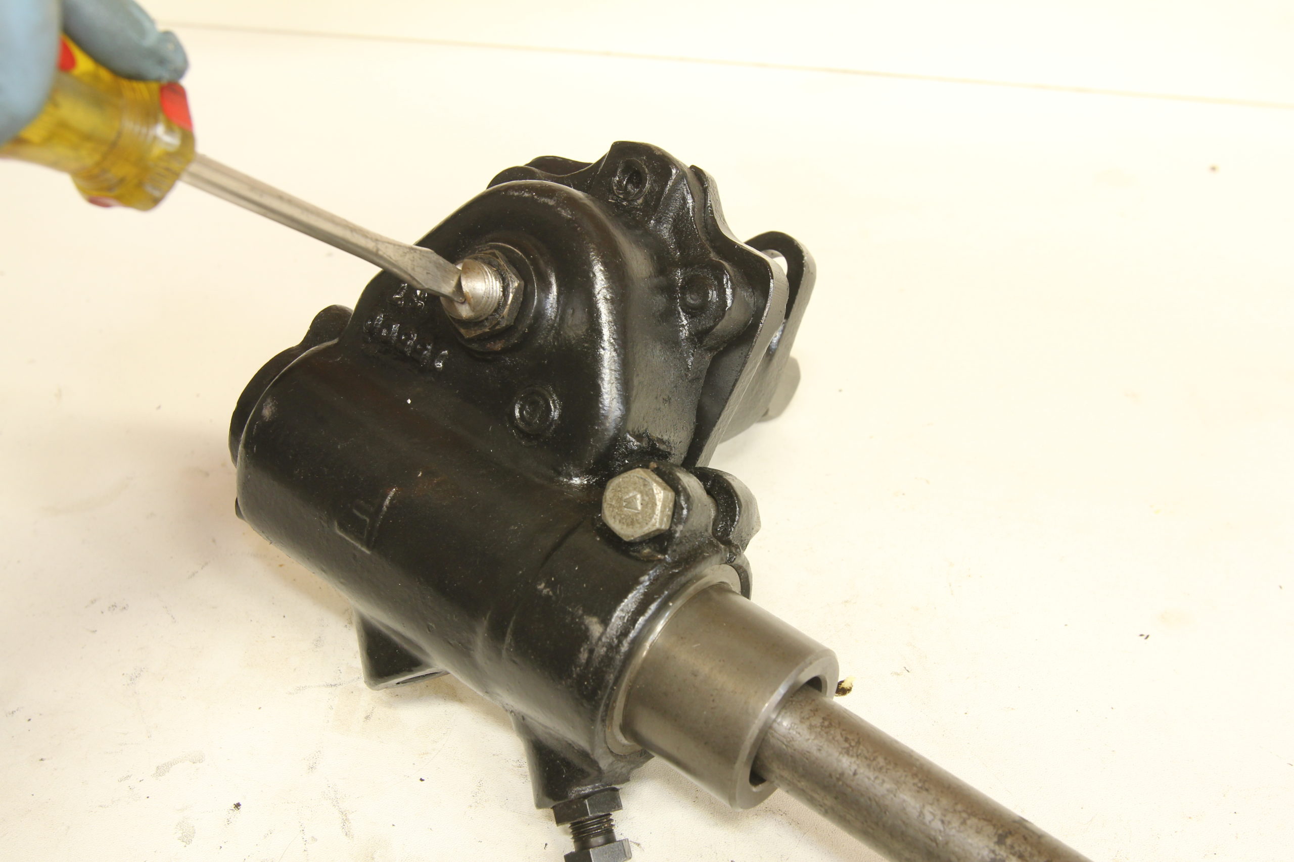
Next, the end play of the sector shaft is adjusted.
This adjustment is made by moving the sector in and out of the housing while slowly tightening the sector shaft end play adjusting screw. Once the end play is removed, the lock nut is tightened.
Next, we’re going to adjust the centralization of the sector to the worm. This adjustment centers the sector teeth to the worm and is necessary when the sector housing or sector itself is replaced. First, the pitman arm is installed on the end of the sector. The steering shaft is then spun to its center of rotation. At 1/2 turn in either direction, the pitman arm is checked for play.
The goal is to equalize this play by adjusting the centering adjusting rivet on the steering box. With this adjustment made, it’s time to adjust the sector worm mesh.
The sector worm mesh adjustment is made by loosening the three housing cover nuts as well as the housing cover adjusting nut 1/4 turn. Next, the eccentric adjusting sleeve nut is tightened very gradually while the pitman arm is rotated to detect sector play.When all play is removed, the housing cover adjusting nut is tightened first, followed by the other three housing nuts. The steering shaft should rotate from stop to stop without any binding if adjusted properly with zero lash when centered.
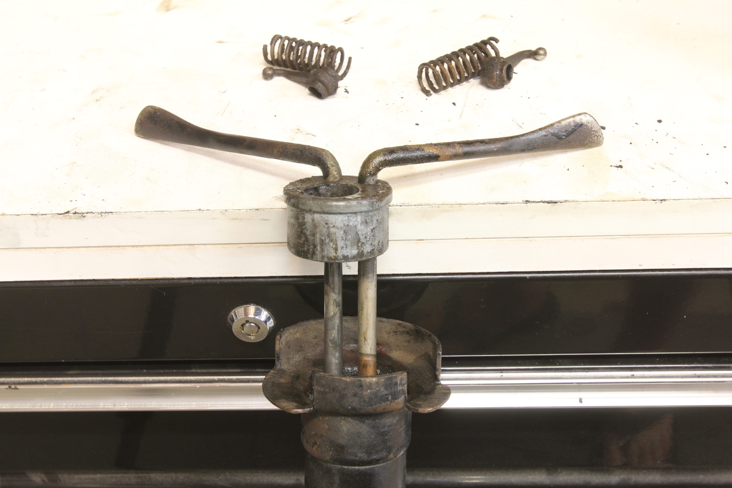
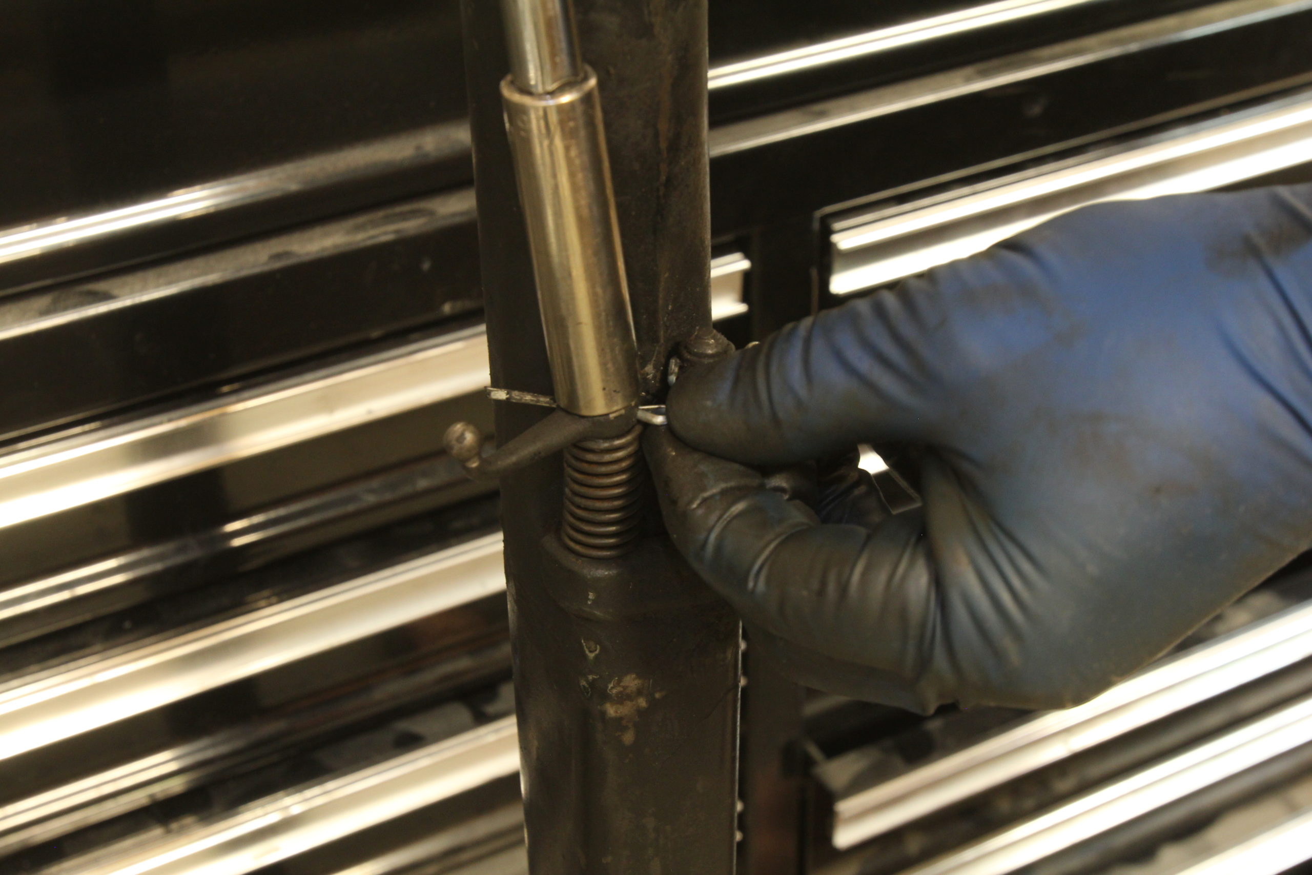
While we had the column out of the car, we figured we might as well replace the upper column bushing as well. This required removing the control rods, arms, and springs. The control arms are attached to the control rods via small pins which are easily sheared using a hammer and a 3/16-inch socket.
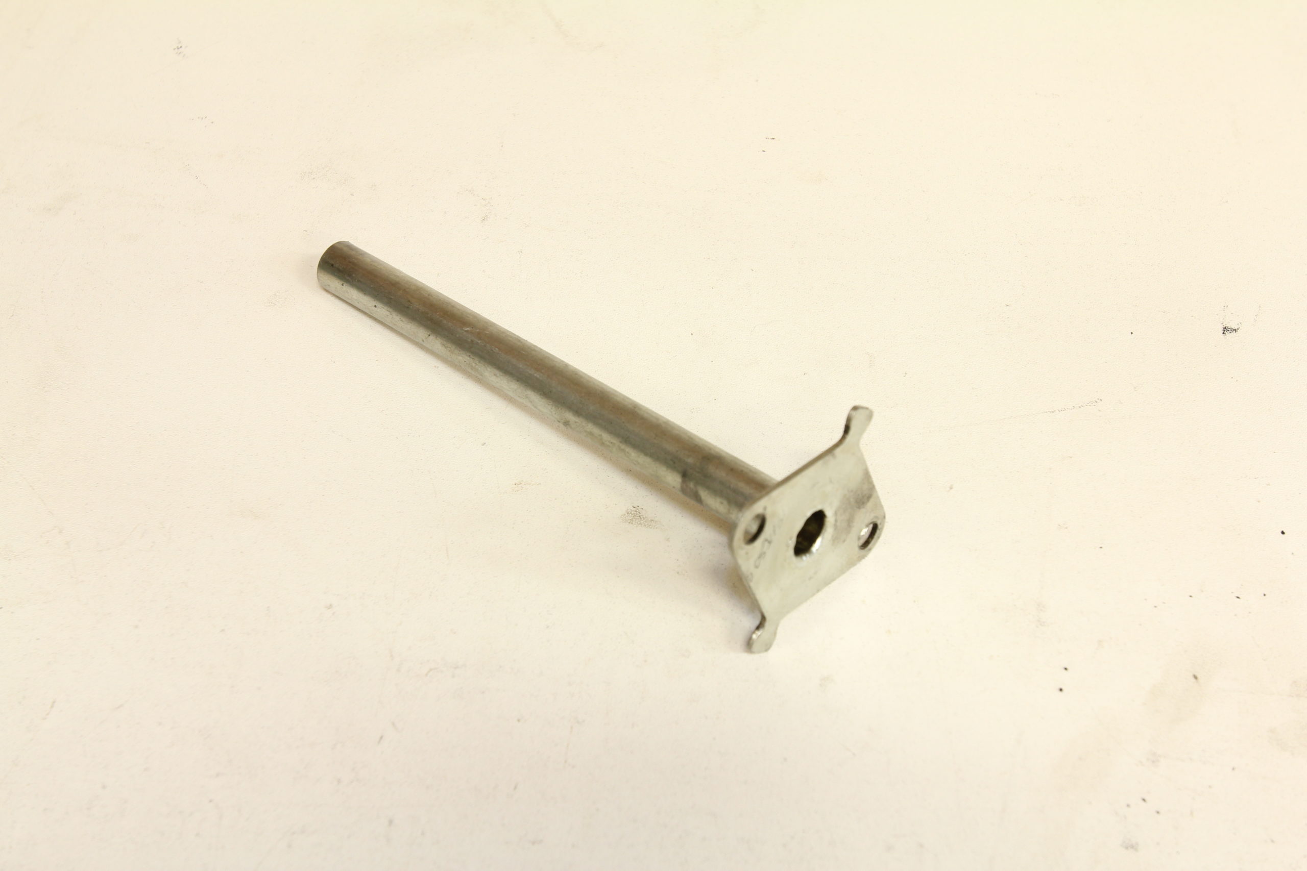
Here’s the assembly being removed from the stock column. That’s the old upper column bushing attached to the control rods.
With the new upper column bushing and control rods in place, the control arms are installed using cotter pins instead of the stock pins. Be sure to install the anti-vibration rubber sleeves on both control rods before reassembly.
The original end plate was known to be a leaky problem so this modified end plate with its long oil retainer tube has become industry standard. With this new style end plate, the orifice where the horn rod passes through the end plate is above the oil level in the steering box, preventing any steering box oil from leaking into the wiring harness and light switch.
The new, modified end plate goes on before the stock light switch bracket is installed, gaskets, RTV and all.
And with that, our newly rebuilt steering box is ready to go back in the car to serve another 90 years or service!
Related posts:
How to Rebuild a 1932 Ford Model B Zenith Carburetor for a Model A 4-Banger How to Rebuild a 1932 Ford Model B Zenith Carburetor for a Model A 4-Banger Motor Big Improvements for the Little Banger By Ryan Manson * clampdowncomp@gmail.com When Ford introduced the Model A in late 1927, it was remarkably different from other automobiles offered at the time, even Ford’s own...
Installing an Overdrive T5 Transmission in a Model A Ford Installing an Overdrive T5 Transmission in a Model A Ford Five Forward Gears for a Model A By Ryan Manson * clampdowncomp@gmail.com A Model A Ford can be one of the simplest machines in which to work. That’s a good thing becuase if you own one, chances are there’s something...
Dashing Debonair Installing a 1952 Pontiac dash in a 1952 Ford F1 pickup truck Dashing Debonair By Ryan Manson * clampdowncomp@gmail.com It’s not uncommon in our hobby to see a car that has been customized to such an extent that it makes it quite hard for not only the newcomer but even...